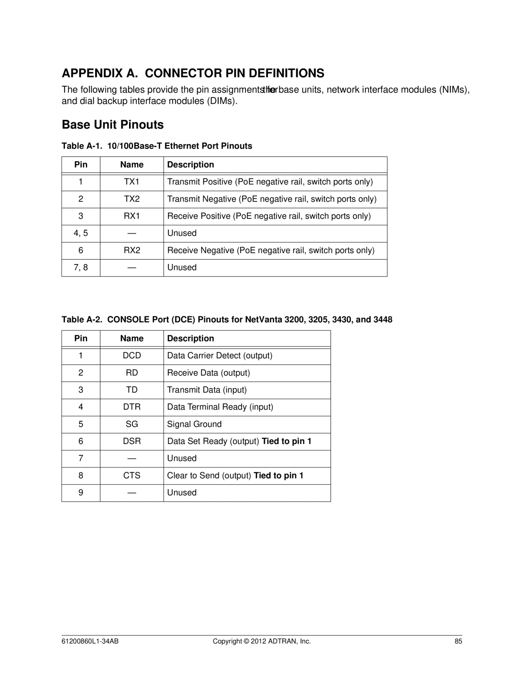
1203860G1, 1202872L1, 1203870G1, 1202880E1, 1202820G1 specifications
The ADTRAN 3448 is a prominent solution in the realm of network connectivity, designed primarily for delivering high-performance broadband services. This device is part of ADTRAN's extensive portfolio aimed at supporting both residential and business applications while leveraging advanced technologies to ensure optimal performance and reliability.One of the main features of the ADTRAN 3448 is its robust architecture, which supports a multitude of deployment scenarios. It is designed to facilitate a scalable network infrastructure, enabling service providers to cater to a diverse range of customer demands efficiently. With its ability to handle multiple types of services, the ADTRAN 3448 is particularly well-suited for environments that require both voice and data transmission.
The device utilizes cutting-edge technologies, including VDSL2 and G.fast for high-speed broadband delivery. These technologies enable the ADTRAN 3448 to maintain high data rates over existing copper infrastructure, maximizing the utility of legacy cabling without necessitating expensive overhauls. This aspect is especially crucial for rural and underserved areas, where the cost of fiber deployment can be prohibitive.
In terms of characteristics, the ADTRAN 3448 offers high-density service capabilities, with support for a significant number of subscribers per unit. This feature allows for efficient use of physical resources and supports the growing demand for bandwidth driven by streaming services, cloud applications, and the Internet of Things (IoT). Moreover, with integrated support for various broadband protocols, the device can seamlessly switch between different service types, providing flexibility in service offerings.
The ADTRAN 3448 is built with advanced management capabilities, including remote monitoring and diagnostics. This allows service providers to maintain network integrity and rapidly resolve issues without needing to dispatch technicians to the field. Additionally, its modular design ensures that as network demands grow, operators can upgrade components without replacing the entire system.
Security features are also a fundamental aspect of the ADTRAN 3448, addressing the increasing need for secure communications in today's digital landscape. With built-in encryption and secure access controls, the device helps protect sensitive data, ensuring that service providers can meet compliance requirements while delivering reliable services.
In summary, the ADTRAN 3448 stands out as a versatile and powerful tool for network operators looking to enhance their service offerings. Its combination of advanced technologies, high-density capabilities, flexible service support, and robust management features make it an ideal choice for a wide range of applications, fulfilling the increasing demands of modern connectivity.