Table 3. Pinout Connectors for RJ-48 T1
Interface
PIN | NAME | DESCRIPTION | |
|
|
| |
1 | R1 - RING1 | Receive data from | |
Network DS1 | |||
|
| ||
|
|
| |
2 | T1 - TIP1 | Receive data from | |
Network DS1 | |||
|
| ||
|
|
| |
3 | UNUSED | - | |
|
|
| |
4 | R - RING | Transmit data to | |
Network DS1 | |||
|
| ||
|
|
| |
5 | T - TIP | Transmit data to | |
Network DS1 | |||
|
| ||
|
|
| |
6, 7, 8 | UNUSED | - | |
|
|
|
Table 4. LED Indication
LED | Condition | Description | |
|
|
| |
| Off: | No power. | |
| Red: | Unit in Red Alarm (T1 | |
Network |
| down or not connected). | |
Yellow: | Receiving Yellow Alarm | ||
T1 | |||
| (far end unit in Red alarm). | ||
|
| ||
| Green: | Normal Operation. | |
| Flashing Green: | Network T1 in Test. | |
|
|
|
4. TESTING
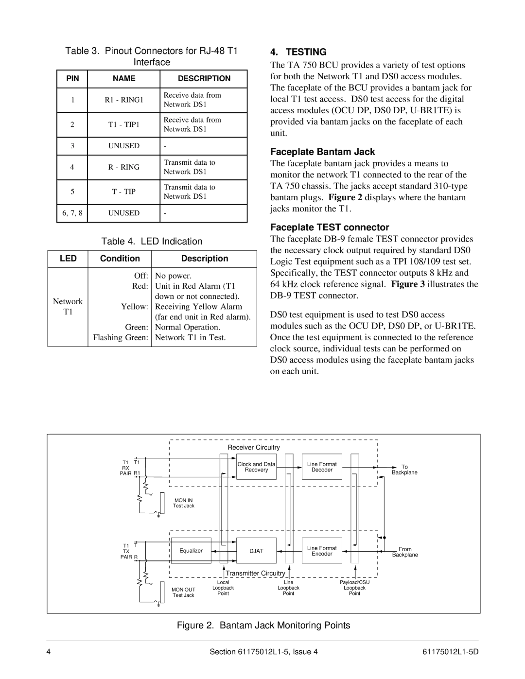
The TA 750 BCU provides a variety of test options for both the Network T1 and DS0 access modules. The faceplate of the BCU provides a bantam jack for local T1 test access. DS0 test access for the digital access modules (OCU DP, DS0 DP,
Faceplate Bantam Jack
The faceplate bantam jack provides a means to monitor the network T1 connected to the rear of the TA 750 chassis. The jacks accept standard
Faceplate TEST connector
The faceplate
64 kHz clock reference signal. Figure 3 illustrates the
DS0 test equipment is used to test DS0 access modules such as the OCU DP, DS0 DP, or
|
| Receiver Circuitry |
|
| |
T1 | T1 |
| Clock and Data | Line Format | To |
RX |
|
| |||
|
| Recovery | Decoder | ||
PAIR R1 |
| Backplane | |||
|
|
| |||
| MON IN |
|
|
|
|
| Test Jack |
|
|
|
|
T1 | T |
|
| Line Format | From |
TX | Equalizer |
| DJAT | ||
PAIR R |
|
| Encoder | Backplane | |
|
|
|
| ||
|
| Transmitter Circuitry |
|
| |
|
| Local | Line |
| Payload/CSU |
| MON OUT | Loopback | Loopback |
| Loopback |
| Point | Point |
| Point | |
| Test Jack |
| |||
|
|
|
|
| |
Figure 2. Bantam Jack Monitoring Points
4 | Section |