Manuals
/
ADTRAN
/
Computer Equipment
/
Network Card
ADTRAN
750
specifications
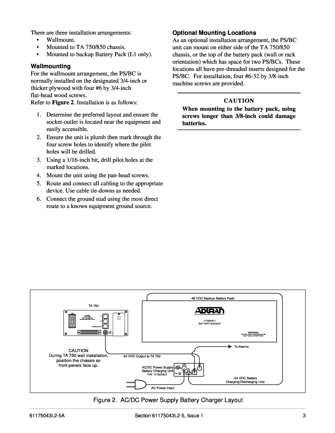
Wallmounting, Optional Mounting Locations
Models:
750
1
3
4
4
Download
4 pages
57.6 Kb
1
2
3
4
Specification
Install
Alarm Relay And Alarm Signal
Page 3
Image 3
Page 2
Page 4
Page 3
Image 3
Page 2
Page 4
Contents
Revision History
Section 61175043L2-5A Issue 1, June CLEI Code # SIMPAADA
Features
1. GENERAL
Status LED
Alarm and Battery Disconnect Relays
3. INSTALLATION
Fuse
Optional Mounting Locations
Wallmounting
Grounding
4. SPECIFICATIONS
5. MAINTENANCE
6. WARRANTY AND CUSTOMER SERVICE
Top
Page
Image
Contents