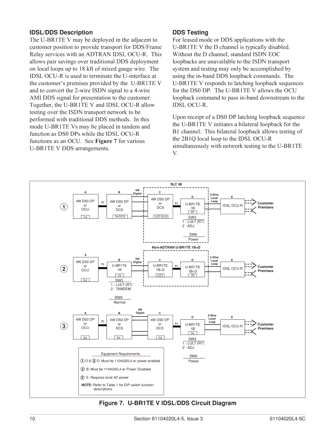
D4 U-BR1TE V specifications
ADTRAN D4 U-BR1TE V is a state-of-the-art broadband networking solution designed to support next-generation services with a focus on reliability, flexibility, and high-speed connectivity. As telecommunications companies strive to meet the ever-increasing demand for bandwidth, the D4 U-BR1TE V stands out as a powerful tool that enables service providers to deliver superior services to their customers.One of the main features of the ADTRAN D4 U-BR1TE V is its versatility in deployment options. This device can be used in various environments, including central offices, remote locations, and outdoor settings. It supports multiple access technologies, such as VDSL2, ADSL2+, and Ethernet, allowing operators to choose the best technology for their specific needs. This flexibility ensures that service providers can efficiently leverage their existing infrastructure while expanding their service offerings.
The D4 U-BR1TE V is equipped with advanced vectoring technology that significantly reduces crosstalk interference, thereby enhancing the overall performance and capacity of DSL connections. This allows operators to extend the reach of their broadband services while delivering higher speeds to end-users. Alongside vectoring, it incorporates G.fast technology, enabling ultra-fast broadband speeds over short copper lines, making it ideal for dense urban areas or multi-dwelling units where bandwidth demand is highest.
In addition to its robust performance capabilities, the ADTRAN D4 U-BR1TE V is designed with operational simplicity in mind. It features an intuitive graphical user interface that streamlines management and monitoring tasks, reducing the burden on network operations teams. Furthermore, its support for cloud-based management platforms allows service providers to automate network monitoring and troubleshooting, ensuring high service levels and quick resolution of issues.
Another notable characteristic of the D4 U-BR1TE V is its scalability. Service providers can easily expand their network by adding additional units as demand grows, ensuring that they can meet the future needs of their customers without extensive overhauls or infrastructure upgrades.
In conclusion, the ADTRAN D4 U-BR1TE V represents a significant advancement in broadband technology. By combining flexibility, high performance, and ease of management, it empowers service providers to deliver enhanced broadband experiences to their customers while efficiently managing their network resources. With its comprehensive feature set and future-proof capabilities, it is an essential component for operators seeking to stay competitive in the increasingly demanding telecommunications landscape.

