Section
Table B. ACT PSU Specifications
Input | DC Voltage | |
| Current | |
| 3.0 A | |
| Ringing Voltage | 0 Vrms to 120 Vrms |
| Current | 105 Vrms, nominal |
| 0.25 A | |
|
|
|
Output | +5 V | +5 VDC ± 5% |
|
| 4 A, maximum |
| +12 V | +12 VDC ± 10% |
|
| 1 A, maximum |
| ||
|
| 1 A, maximum |
| ||
|
| 2 A, maximum |
| 20 Hz | 0 to 120 Vrms |
|
| 105 V, nominal |
|
| 0.25 A, maximum |
|
|
|
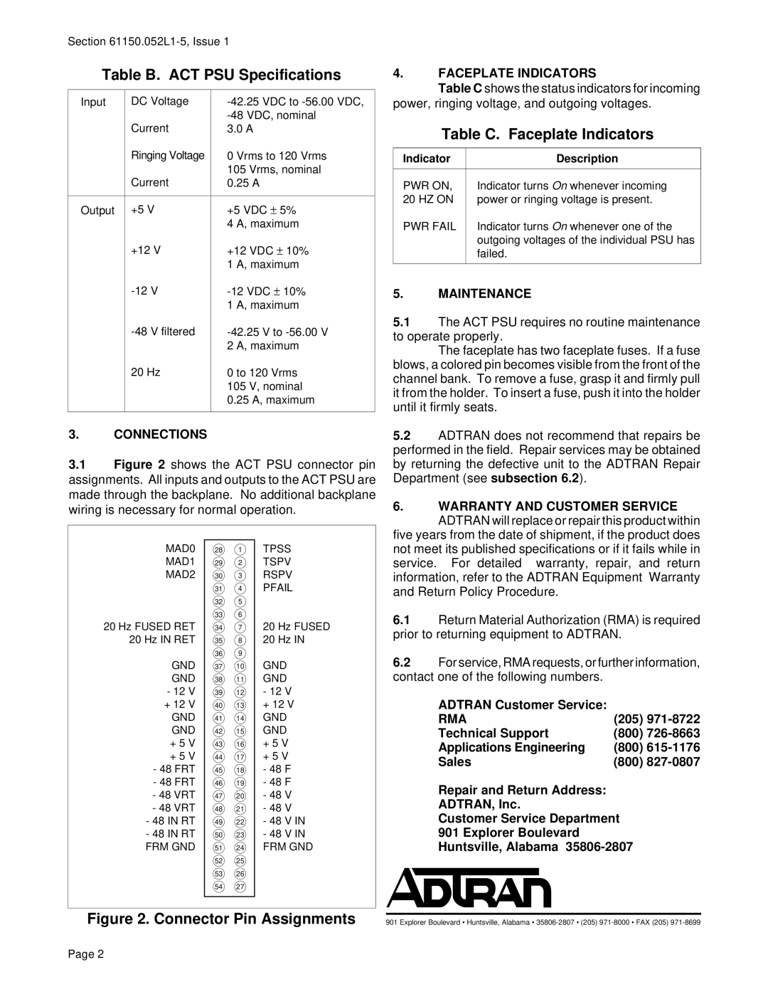
3.CONNECTIONS
3.1Figure 2 shows the ACT PSU connector pin assignments. All inputs and outputs to the ACT PSU are made through the backplane. No additional backplane wiring is necessary for normal operation.
4.FACEPLATE INDICATORS
Table C shows the status indicators for incoming
power, ringing voltage, and outgoing voltages.
Table C. Faceplate Indicators
Indicator | Description |
|
|
PWR ON, | Indicator turns On whenever incoming |
20 HZ ON | power or ringing voltage is present. |
PWR FAIL | Indicator turns On whenever one of the |
| outgoing voltages of the individual PSU has |
| failed. |
|
|
5.MAINTENANCE
5.1The ACT PSU requires no routine maintenance to operate properly.
The faceplate has two faceplate fuses. If a fuse blows, a colored pin becomes visible from the front of the channel bank. To remove a fuse, grasp it and firmly pull it from the holder. To insert a fuse, push it into the holder until it firmly seats.
5.2ADTRAN does not recommend that repairs be performed in the field. Repair services may be obtained by returning the defective unit to the ADTRAN Repair Department (see subsection 6.2).
6.WARRANTY AND CUSTOMER SERVICE ADTRAN will replace or repair this product within
MAD0
MAD1
MAD2
20 Hz FUSED RET
20 Hz IN RET
GND
GND
- 12 V
+ 12 V
GND
GND
+ 5 V
+ 5 V - 48 FRT - 48 FRT - 48 VRT - 48 VRT
-48 IN RT
-48 IN RT FRM GND
281
292
303
314
325
336
347
358
369
3710
3811
3912
4013
4114
4215
4316
4417
4518
4619
4720
4821
4922
5023
5124
5225
5326
5427
TPSS
TSPV
RSPV
PFAIL
20 Hz FUSED
20 Hz IN
GND
GND
-12 V + 12 V GND GND + 5 V + 5 V
-48 F
-48 F
-48 V
-48 V
-48 V IN
-48 V IN FRM GND
five years from the date of shipment, if the product does not meet its published specifications or if it fails while in service. For detailed warranty, repair, and return information, refer to the ADTRAN Equipment Warranty and Return Policy Procedure.
6.1Return Material Authorization (RMA) is required prior to returning equipment to ADTRAN.
6.2For service, RMA requests, or further information, contact one of the following numbers.
ADTRAN Customer Service: |
|
RMA | (205) |
Technical Support | (800) |
Applications Engineering | (800) |
Sales | (800) |
Repair and Return Address:
ADTRAN, Inc.
Customer Service Department
901 Explorer Boulevard
Huntsville, Alabama
Figure 2. Connector Pin Assignments
901 Explorer Boulevard • Huntsville, Alabama •
Page 2