ISU
Part Numbers
Trademarks
Page
FCC ID HDC1202029TL
Canadian Emissions Requirements
Canadian Equipment Limitations
Table of Contents
Near-End Block Errors/Far-End Block Errors NEBE/FEBE
Txinit Txfa TXADD01 Txdeq Tanull Tcid
If Self Test Fails If The ISU 128 Does Not Read Ready
Environmental Physical Power
Table of Contents
List of Figures
Figure E-1 EIA-232/RS-530 Interface 115
List of Tables
List of Tables
Isdn Overview
Adtran ISU
ISU 128 Rear Panel
ISU 128 Front Panel DTE Indicators
Indicator Definition
ISU 128 Interoperability
Switched
Recommended Operating Protocols
Recommended Operating Modes
Understanding Isdn and the ISU
Ordering Isdn Using Iocs
Chapter Isdn Ordering Codes IOCs
Capability S
Capability R
Capability B
Capability C
Chapter Installation
Network Connection
Dial Interface Connection
DTE Data Connection
Maximum DTE Interface Cable Lengths
Maintenance Interface
Installation
Chapter Operation
Menu Navigation
Config Configuration
Getting Started
Status Buffer
Status Test
Status Screen
VT 100 Terminal Menu Support
VT 100 Status Screen
Configuration Screen
VT 100 Configuration Screen
Test Options
Chapter Testing
VT 100 Test Screen
Loopback DTE
Loopback Network
Loopback Protocol
Test Menu Tree
Loopback Remote
Loopback Disable
Test Remote
Near-End Block Errors/Far-End Block Errors NEBE/FEBE
Press Cancel to exit any of these options
Software Version
DDS+V54 Accept
Dial Line Operation
Chapter Configuration
Dial Line Menu Tree
Call Type
Switch Protocol
Speech
Data 64 kbps default
Setting the Spid
Terminal Identification
Audio
Setting the LDN
Configur
=AT&T 5ESS
Configuration
Dial options
Front Panel
RS-366
Dial Options, RS-366 Menu Tree
AT Commands
Sec or EON default
Sec or EON
Wait for EON
Using AT Commands
Using S-Registers
Dialing a Call Using the AT Command Processor
Reading S-Registers
Reading S-Register Strings
Changing S-Registers
25 bis
Dial Options, V.25 bis Menu Tree
Async Dialing
Dial Line, Auto Answer Menu Tree
Data Bits Menu Tree
Disabled
Bis Async Menu Tree
Sync Hdlc Dialing
Sync Bisync Dialing
Auto Answer
Enabled
Dump all calls
No Answer Tone Default
Answer Tone
Incoming Tone
Outgoing Tone
Connect Timeout
Connect Timeout Menu Tree
Call Screening
Call Screening Menu Tree
Select Ansr if SN0. . .9 under Call Screening
Leased Line Service
Clock ModeSlave/Master
Leased Line Menu Tree
Limited Distance Modem Application
Channel Rate
Leased Application with Channel Banks
DTE Options
Bit Rate
Asynchronous DTE Options Menu Tree
Synchronous DTE Options Menu Tree
Connector Type
RTS Options
CTS Options
CD Options
Flow Control Asynchronous Data Format
DSR Options
Flow Control Menu Tree
Transmit Clock Synchronous Data Format
Data Format Asynchronous
Data Format Menu Tree
Configuration
Chapter Protocol Options
Protocol Options
Bonding Mode
Clear Channel
Txinit
Bonding Mode 1 Protocol Menu Tree
Txfa
120
TXADD01
Txdeq
Tanull
Error Control Menu Tree
Error Control
110
Compression
Compression Menu Tree
Microcom Network Protocol Block Size MNP Blk
MNP Block Size Menu Tree
Link
DSU 57.6 Async
Simple Adtran Protocol SAP
Fallback
Rate Adaption Protocols
Fallback Menu Tree
=Protocol =V.34
Point-to-Point PPP Async-to-Sync
PPP Menu Tree
Point-to-Point Protocol PPP
Multilink Point-to-Point Protocol MP
PPP with Compression
Protocol Options
Chapter Quick Setup
Quick Setup Configuration
Quick Setup
Dial 56K sync
Dial 64K sync
Dial 112K sync
Dial 128K sync
Dial PPP
V34 115.2 async
Dial 57.6 asyn
Dial 115.2 asyn
Fallback 57.6k
Leased 128K
More
Ldm 128 Master
Factory Setup
AT&T 5ESS
Dialing Options
Chapter Dial Options
VT 100 Terminal Dial Options Screen
Hang Up Line
Dial Number
Redial Last Number
Answer Call
Store/Review Number
Dial Options
Remote Configuration
Chapter Remote Configuration
Configuring with AT Commands
Remote Configuration Menu Path
Remote Configuration Screen
Configure Remote Unit
Remote Unit Configuration Screen
Remote Testing
Set Password
Loopback Remote 1B
Test Menu Path
Loopback Remote 1B Set Password Screen
Remote Configuration
If Self Test Fails
Chapter Troubleshooting
If the ISU 128 does not Read Ready
CONFIG, Netw. options, Dial Line, is selected on the menu
CONFIG, Netw. options, Dial Line, Switch protocl
CONFIG, Netw. options, Dial line, Switch protocl
Troubleshooting
Troubleshooting
Chapter Specifications
Specifications and Features
Switch Compatibility
Rate Adaption
Interoperability
Channel Aggregation
Environmental
Power
Physical
Specifications
Appendix a AT Commands
Command Function
Carrier Detect CD Control Line Options
Clear-To-Send CTS Control Line Options
AT Command Response Message Types
Compression Block Size Options
Appendix A. AT Commands
Disconnecting
Appendix B Current Status Messages
NET REM Loopback
NET EOC Loopback
Ringing
Bonding
Clear Chan
Dstop
Fallback
Appendix B. Current Status Messages
Accessinfodiscarded
Appendix C Status Buffer Messages
Badinfoelem
Bearcapnotavail
Bonding +
Busy
Callrejected
Capnotimplemented
Chandoesnotexist
Channotimplemented
Fallback Error
Dpump END Rcvd
Facilitynotimplement
Facilityrejected
Invalidelemcontents
Incommingcallbarred
Incompatibledest
Invalidcallref
LDN TOO Long
Mandatoryielenerr
Mandatoryiemissing
Network Busy
Protocolerror
Noroute
Nouserresponding
Normalclearing
Servicenotavail
Timerexpiry
Source not Isdn
Temporaryfailure
TX Flow Error
Unassignednumber
Unspecifiedcause
Userbusy
106
Appendix D
Register List
Escape Time
Misc Bits
Async Bonding
MSG Bits
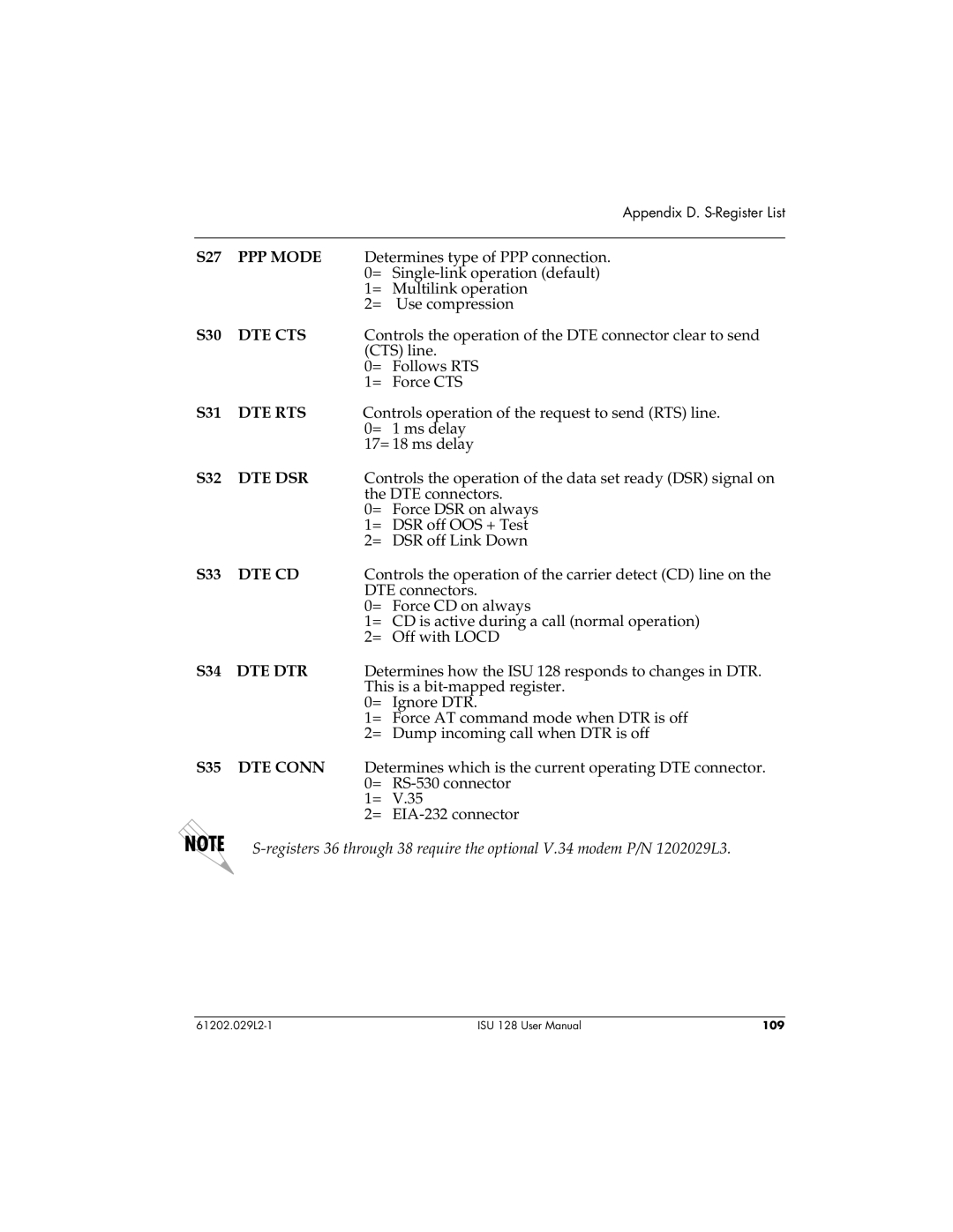
PPP Mode
DTE CTS
DTE RTS
DTE DSR
Error
Correction
Compression
V34 Block Size
V25 Mode
Line Mode
Bond TXADD01
Bond Txdeq
Switch
Dial Mode
Line Clock
Protocol
DTE Mode
DDS Test
SPID1 LOC
SPID2 LOC
Data Bits
DTE Parity
DTE Stop
DTE Flow
EIA-232/RS-530 Interface
Appendix E Connector Pinouts
EIA-232 Interface
RS-530 Interface
Interface
ST-B
RS-366 Interface
RJ-45 Interface
Maintenance Port
Figure E-5
120
AMI
Ansi
BRI
Ccitt
Lata
MNP
Nebe
PBX
Bearer service
Glossary
DDS
Isdn
NT2
TE1
2B+D
129
130
Index
DTE
Isdn
Ppp
Tanull 50 Tcid
136
Product Support Information
Presales Inquiries and Applications Support
Post-Sale Support
Repair and Return