1.0GENERAL
1.01Unit Overview
The ADTRAN NT1 Type 400 provides a basic rate interface be- tween the customer’s ISDN Terminal Equipment (TE) and the ISDN Network. Two interfaces are provided for this purpose: con- nection to the ISDN network is made by the “U” interface and connection to the customer's ISDN TE is made by the S/T inter- face.
The NT1 Type 400 is available in two configurations:
•The NT1 Type 400 Standalone with an internal power supply, Part No. 1212.016L1.
•The NT1 Type 400 Circuit Pack, Part No. 1212.010.
The ADTRAN NT1 Type 400 Standalone consists of two parts, a metal housing containing the power supply, connectors, and the NT1 Type 400 Circuit Pack. The Circuit Pack can be removed from the housing by removing the plastic front panel and sliding the unit out of the housing. This allows access to the option switches which may be reset by the customer. The NT1 Type 400 Circuit Pack can also be purchased as a separate unit and mounted in a Type 400 NCTE rack, as indicated in APPENDIX A.
LED Indicators
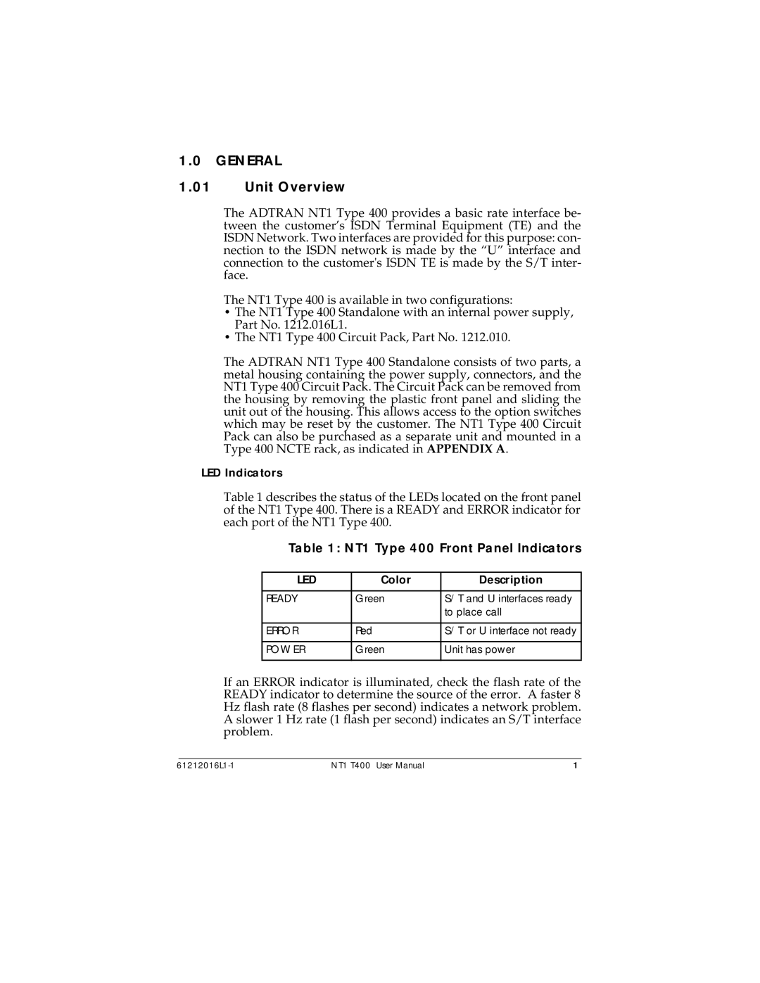
Table 1 describes the status of the LEDs located on the front panel of the NT1 Type 400. There is a READY and ERROR indicator for each port of the NT1 Type 400.
Table 1: NT1 Type 400 Front Panel Indicators
LED | Color | Description |
|
|
|
READY | Green | S/T and U interfaces ready |
|
| to place call |
|
|
|
ERROR | Red | S/T or U interface not ready |
|
|
|
POWER | Green | Unit has power |
|
|
|
If an ERROR indicator is illuminated, check the flash rate of the READY indicator to determine the source of the error. A faster 8 Hz flash rate (8 flashes per second) indicates a network problem. A slower 1 Hz rate (1 flash per second) indicates an S/T interface problem.
NT1 T400 User Manual | 1 |