G. Full G.703 Service
If this quick key command is selected, the cross- connect map will automatically configure the time slots for Full G.703 service, and the framing will be set for transparent. Refer to the Typical Applications subsection for more information.
N. Full Nx64k Service
If this quick key command is selected, the
Tab. Select SHDSL or G.703 Timeslots
The tab key moves the cursor between the SHDSL and G.703 sections of the
Arrow Keys. Move Cursor
The arrow keys allow movement between the individual time slots.
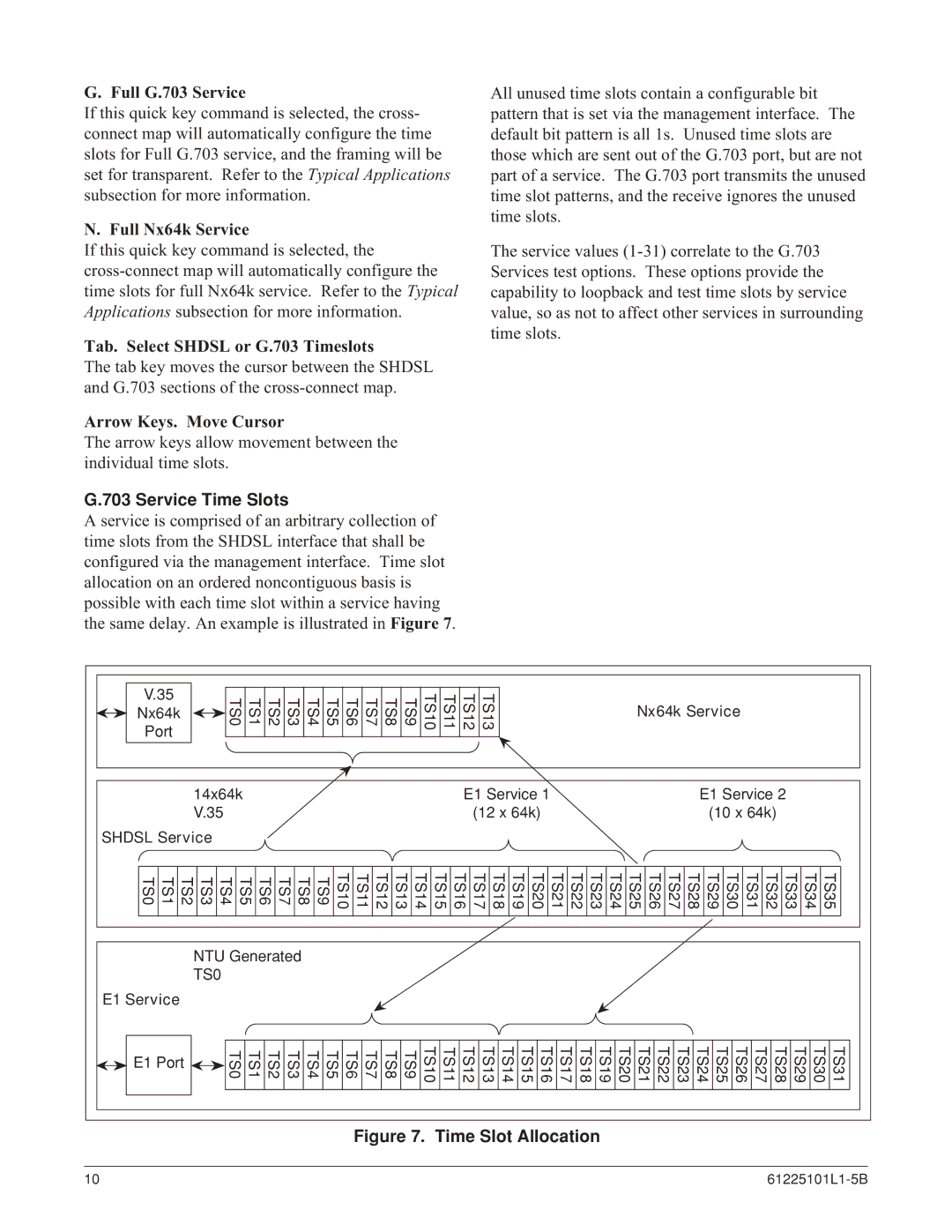
G.703 Service Time Slots
A service is comprised of an arbitrary collection of time slots from the SHDSL interface that shall be configured via the management interface. Time slot allocation on an ordered noncontiguous basis is possible with each time slot within a service having the same delay. An example is illustrated in Figure 7.
All unused time slots contain a configurable bit pattern that is set via the management interface. The default bit pattern is all 1s. Unused time slots are those which are sent out of the G.703 port, but are not part of a service. The G.703 port transmits the unused time slot patterns, and the receive ignores the unused time slots.
The service values
V.35 |
| TS0 | TS1 | TS3 TS2 | TS4 | TS5 | TS6 | TS7 | TS8 | TS9 | TS10 | TS11 | TS13 TS12 |
|
|
|
|
| Nx64k Service |
|
|
|
|
Nx64k |
|
|
|
|
|
|
|
|
|
| |||||||||||||
Port |
|
|
|
|
|
|
|
|
|
|
| ||||||||||||
|
|
|
|
|
|
|
|
|
|
|
|
|
|
|
|
|
|
|
|
|
|
| |
|
| 14x64k |
|
|
|
|
|
|
|
|
|
| E1 Service 1 |
|
|
|
|
| E1 Service 2 |
|
|
|
|
|
| V.35 |
|
|
|
|
|
|
|
|
|
| (12 x 64k) |
|
|
|
|
| (10 x 64k) |
|
|
|
|
SHDSL Service |
|
|
|
|
|
|
|
|
|
|
|
|
|
|
|
|
|
|
|
|
| ||
TS1 TS0 | TS2 | TS20 TS19 TS18 TS17 TS16 TS15 TS14 TS13 TS12 TS11 TS10 TS9 TS8 TS7 TS6 TS5 TS4 TS3 | TS21 | TS23 TS22 | TS24 | TS32 TS31 TS30 TS29 TS28 TS27 TS26 TS25 | TS33 | TS34 | TS35 | ||||||||||||||
|
| NTU Generated |
|
|
|
|
|
|
|
|
|
|
|
|
|
|
|
|
|
|
| ||
|
| TS0 |
|
|
|
|
|
|
|
|
|
|
|
|
|
|
|
|
|
|
|
|
|
E1 Service |
|
|
|
|
|
|
|
|
|
|
|
|
|
|
|
|
|
|
|
|
|
|
|
E1 Port | TS0 | TS1 | TS3 TS2 | TS4 | TS5 | TS6 | TS7 | TS8 | TS9 | TS10 | TS11 | TS16 TS15 TS14 TS13 TS12 | TS20 TS19 TS18 TS17 | TS28 TS27 TS26 TS25 TS24 TS23 TS22 TS21 | TS31 TS30 TS29 | ||||||||
|
| ||||||||||||||||||||||
Figure 7. Time Slot Allocation
10 |
