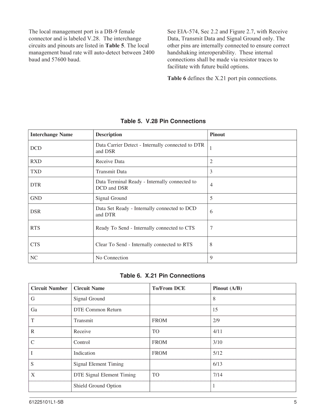
The local management port is a
See
Table 6 defines the X.21 port pin connections.
Table 5. V.28 Pin Connections
Interchange Name | Description | Pinout | |
|
|
| |
DCD | Data Carrier Detect - Internally connected to DTR | 1 | |
| and DSR |
| |
|
|
| |
RXD | Receive Data | 2 | |
|
|
| |
TXD | Transmit Data | 3 | |
|
|
| |
DTR | Data Terminal Ready - Internally connected to | 4 | |
DCD and DSR | |||
|
| ||
|
|
| |
GND | Signal Ground | 5 | |
|
|
| |
DSR | Data Set Ready - Internally connected to DCD | 6 | |
and DTR | |||
|
| ||
|
|
| |
RTS | Ready To Send - Internally connected to CTS | 7 | |
|
|
| |
CTS | Clear To Send - Internally connected to RTS | 8 | |
|
|
| |
NC | No Connection | 9 | |
|
|
|
Table 6. X.21 Pin Connections
Circuit Number | Circuit Name | To/From DCE | Pinout (A/B) |
|
|
|
|
|
|
G | Signal Ground |
| 8 |
|
|
|
|
|
|
Ga | DTE Common Return |
| 15 |
|
|
|
|
|
|
T | Transmit | FROM | 2/9 |
|
|
|
|
|
|
R | Receive | TO | 4/11 |
|
|
|
|
|
|
C | Control | FROM | 3/10 |
|
|
|
|
|
|
I | Indication | FROM | 5/12 |
|
|
|
|
|
|
S | Signal Element Timing |
| 6/13 |
|
|
|
|
|
|
X | DTE Signal Element Timing | TO | 7/14 |
|
|
|
|
|
|
| Shield Ground Option |
| 1 |
|
|
|
|
|
|
|
|
|
|
|
5 |
