SW-H1 No. 3 Reserved
Set to "0".
SW-H1 No. 4 Busy tone continuous sound detect time
Set detecting time busy tone continuous sound for 5 seconds or 10 sec- onds.
SW-H1 No. 5 Busy tone detect continuation sound detect during
OGM
Used to detect the continuous tone of specific frequency during OGM output.
ICM
Used to detect the continuous tone of specific frequency during ICM recording.
SW-H1 No. 7 Busy tone detect intermittent sound detect during
OGM
Used to detect the intermitten tone of specific frequency during OGM output.
ICM
Used to detect the intermittent tone of specific frequency during ICM recording.
SW-H2 No. 1, No. 2 Busy tone detection pulse number
Used to set detection of Busy tone intermittent sounds.
SW-H2 No. 3 Fax switching when A.M. full
If the answering machine’s memory (tape) is full and there is no re- sponse, the machine automatically switches to Fax reception.
Set detecting frequency of busy tone continuation sound for 320 ~ 570 Hz or 320 ~ 460 Hz.
SW-H2 No. 5 ~ No. 8 Reserved
Set to "0".
SW-I1 No. 1, No. 2 ICM recording time
Used to select the incoming message recording time among 15sec/ 30sec/60sec/4min.
SW-I1 No. 3, No. 4 A.M. quiet time 1
Used to select four kinds of no sound time (2 sec ~ 5 sec) after reception in the T. A. D mode until OGM is output.
Reception | OGM output | ICM recording |
2 sec~ 5 sec (
Used to select four kinds of no sound time (0 sec ~ 3 sec) after OGM output the T. A. D mode until ICM recording is started.
Reception | OGM output | ICM recording |
0 sec~3 sec (SW-I1 No. 5, No. 6)
Used to turn ON/OFF key input buzzer in the
SW-I1 No. 8 Reserved
Set to “0”.
SW-I2 No. 1 ~ No. 5 A.M. quiet detect time
Used to set no sound time (0 sec - 32 sec) during the T. A. D. mode operation.
SW-I2 No. 6, No. 7 Reserved
Set to “0”.
SW-I2 No. 8 Alarm during two way recording
When set to “1”, alarm sound is given to remote side during two way recording.
SW-I3 No. 1 Max OGM record time
Used to select the maximum OGM recording time (1 = 15 sec, 0 = 60 sec).
SW-I3 No. 2 Reserved
Set to “0”.
SW-I3 No. 3 Two way record function
If this switch is set to “1”, machine doesn’t work two way recording function.
SW-I3 No. 4 Toll saver
Used to turn on the toll saver function. If it is off, the reception frequency in the AM mode is identical with that in the FAX mode.
SW-I3 No. 5, No. 6 Reserved
Set to “0”.
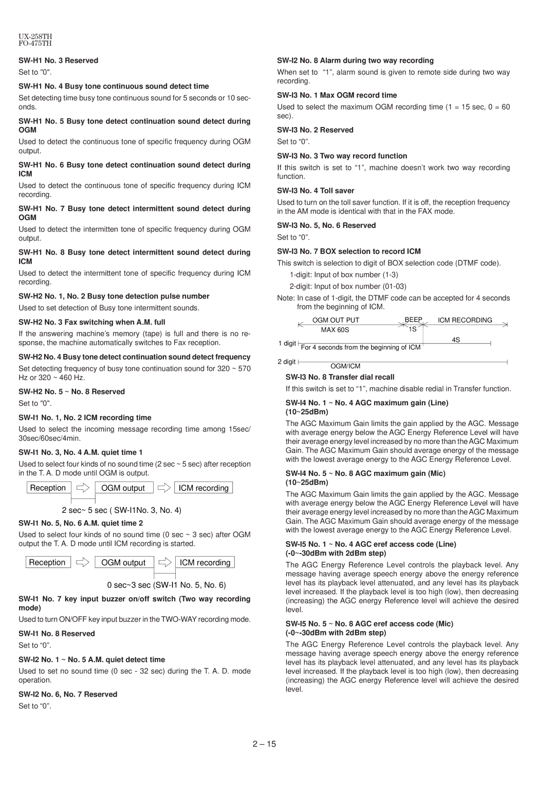
SW-I3 No. 7 BOX selection to record ICM
This switch is selection to digit of BOX selection code (DTMF code).
Note: In case of
|
| OGM OUT PUT |
| BEEP |
| ICM RECORDING |
| ||
|
|
|
| ||||||
1 digit |
| MAX 60S |
| 1S |
| 4S |
|
|
|
|
|
|
|
|
|
|
| ||
| For 4 seconds from the beginning of ICM |
|
|
|
|
| |||
2 digit
OGM/ICM
SW-I3 No. 8 Transfer dial recall
If this switch is set to “1”, machine disable redial in Transfer function.
SW-I4 No. 1 ~ No. 4 AGC maximum gain (Line) (10~25dBm)
The AGC Maximum Gain limits the gain applied by the AGC. Message with average energy below the AGC Energy Reference Level will have their average energy level increased by no more than the AGC Maximum Gain. The AGC Maximum Gain should average energy of the message with the lowest average energy to the AGC Energy Reference Level.
SW-I4 No. 5 ~ No. 8 AGC maximum gain (Mic) (10~25dBm)
The AGC Maximum Gain limits the gain applied by the AGC. Message with average energy below the AGC Energy Reference Level will have their average energy level increased by no more than the AGC Maximum Gain. The AGC Maximum Gain should average energy of the message with the lowest average energy to the AGC Energy Reference Level.
The AGC Energy Reference Level controls the playback level. Any message having average speech energy above the energy reference level has its playback level attenuated, and any level has its playback level increased. If the playback level is too high (low), then decreasing (increasing) the AGC energy Reference level will achieve the desired level.
The AGC Energy Reference Level controls the playback level. Any message having average speech energy above the energy reference level has its playback level attenuated, and any level has its playback level increased. If the playback level is too high (low), then decreasing (increasing) the AGC energy Reference level will achieve the desired level.
2 – 15