[3] Circuit description of TEL/LIU PWB
(1) TEL/LIU block operational description
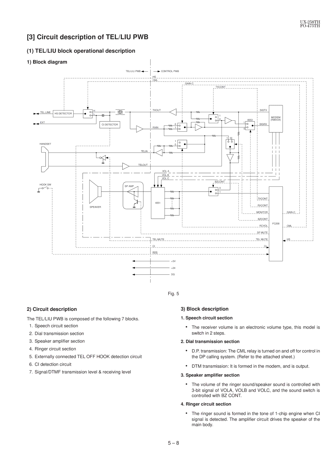
1) Block diagram
TEL/LIU PWB |
|
|
| CONTROL PWB |
|
|
HS
CML
TXCONT
TEL LINE |
| H | TXOUT |
|
HS DETECTOR | L |
|
| |
|
|
| ||
EXT |
| CI DETECTOR |
| 0 |
|
|
| ||
|
|
| RXIN | 1 |
|
|
|
| 1 |
HANDSET |
|
|
| 0 |
|
|
| TELIN |
|
|
|
| TELOUT |
|
|
|
|
| VOL A |
|
|
|
| VOL B |
|
|
|
| VOL C |
HOOK SW |
|
| SP AMP |
|
|
|
|
| |
|
|
| 4051 |
|
|
| SPEAKER |
|
|
TEL MUTE
CI
RHS
+5V
+24
DG
1 |
|
0 |
|
1 | 0 |
BZCONT |
|
0 |
|
1 |
|
4053
1
0
SIGTX
SIGRX
TXCONT
RXCONT
MONITOR
BZCONT
RCVOL
SP MUTE
TEL MUTE
CI
MODEM
(R96V24)
FC200
CML
HS
2) Circuit description
The TEL/LIU PWB is composed of the following 7 blocks.
1.Speech circuit section
2.Dial transmission section
3.Speaker amplifier section
4.Ringer circuit section
5.Externally connected TEL OFF HOOK detection circuit
6.CI detection circuit
7.Signal/DTMF transmission level & receiving level
Fig. 5
3) Block description
1.Speech circuit section
•The receiver volume is an electronic volume type, this model is switch in 2 steps.
2.Dial transmission section
•D.P. transmission: The CML relay is turned on and off for control in the DP calling system. (Refer to the attached sheet.)
•DTM transmission: It is formed in the modem, and is output.
3.Speaker amplifier section
•The volume of the ringer sound/speaker sound is controlled with
4.Ringer circuit section
•The ringer sound is formed in the tone of
5 – 8