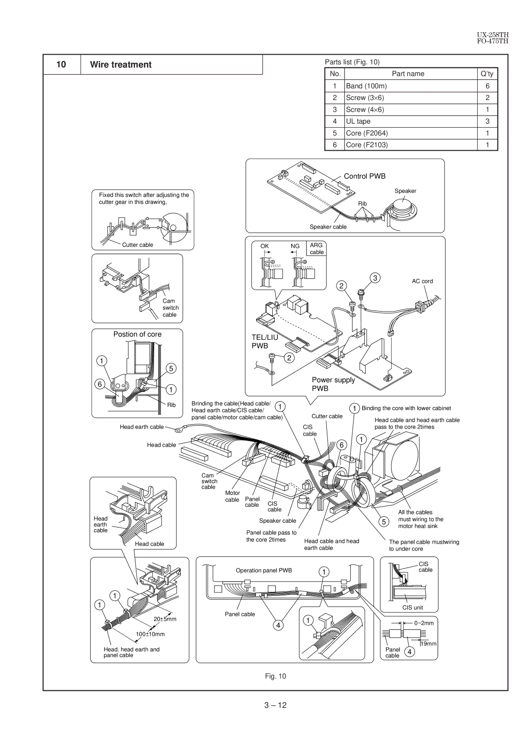
10 | Wire treatment |
|
|
Fixed this switch after adjusting the cutter gear in this drawing,
Parts list (Fig. 10)
No. | Part name | Q’ty |
|
|
|
1 | Band (100m) | 6 |
|
|
|
2 | Screw (3×6) | 2 |
|
|
|
3 | Screw (4×6) | 1 |
|
|
|
4 | UL tape | 3 |
|
|
|
5 | Core (F2064) | 1 |
|
|
|
6 | Core (F2103) | 1 |
Control PWB
Speaker
Rib
Speaker cable
Cutter cable | OK | NG ARG |
|
| cable |
3 | AC cord |
2
Cam switch cable
Postion of core |
| TEL/LIU | ||
|
| |||
|
| PWB |
| |
1 |
|
| 2 | |
|
|
| ||
5 |
|
|
| |
6 |
|
|
| |
1 |
|
|
| |
Rib | Brinding the cable(Head cable/ | 1 | ||
Head earth cable/CIS cable/ | ||||
|
| |||
| panel cable/motor cable/cam cable) | |||
Head earth |
|
|
| |
Head cable |
|
|
| |
| Cam |
|
| |
| switch |
|
| |
| cable |
|
| |
| Motor | Panel |
| |
| cable |
| ||
|
| cable CIS |
| |
|
| cable | ||
Head |
| Speaker cable | ||
earth |
| |||
|
|
| ||
cable |
| Panel cable pass to | ||
|
| |||
Head cable |
| the core 2times | ||
|
|
| ||
| Operation panel PWB | |||
1
Power supply
PWB
1Binding the core with lower cabinet
Cutter cable
Head cable and head earth cable
CISpass to the core 2times cable
1
6
|
| All the cables |
| 5 | must wiring to the |
| motor heat sink | |
|
| |
Head cable and head |
| The panel cable mustwiring |
earth cable |
| to under core |
|
| CIS |
1 |
| cable |
1 |
|
| CIS unit | |
| Panel cable |
| ||
20 5mm | 1 |
| ||
4 | 0~2mm | |||
|
| |||
|
|
| ||
100 10mm |
|
|
|
19mm
Head, head earth and | Panel | 4 |
panel cable | cable |
|
Fig. 10
3 – 12
