The AGC adjusts the amount of gain applied to the incoming message only when the average energy exceeds the AGC Gain Adaptation Threshold. The AGC Gain Adaptation Threshold prevents message background noise from corrupting the gain provided that the AGC Gain Adaptation Threshold is greater than the background noise energy. In the event that a message has background noise energy greater than the AGC Gain Adaptation Threshold, the AGC Gain can be no greater than the AGC Maximum Gain. Note that the AGC Gain Adaptation Threshold must always be greater than the RPACS VOX
The AGC adjusts the amount of gain applied to the incoming message only when the average energy exceeds the AGC Gain Adaptation Threshold. The AGC Gain Adaptation Threshold prevents message background noise from corrupting the gain provided that the AGC Gain Adaptation Threshold is greater than the background noise energy. In the event that a message has background noise energy greater than the AGC Gain Adaptation Threshold, the AGC Gain can be no greater than the AGC Maximum Gain. Note that the AGC Gain Adaptation Threshold must always be greater than the RPACS VOX
SW-I7 No. 1, No. 2 AGC slew rate (Line)
The AGC Slew Rate controls the convergence of the message playback level to the desired playback level. A large slew rate will allow faster convergence and a small slew rate will allow slower convergence.
SW-I7 No. 3, No. 4 AGC slew rate (Mic)
The AGC Slew Rate controls the convergence of the message playback level to the desired playback level. A large slew rate will allow faster convergence and a small slew rate will allow slower convergence.
SW-I7 No. 5 FAX BOX function
FAX BOX function YES/NO is set.
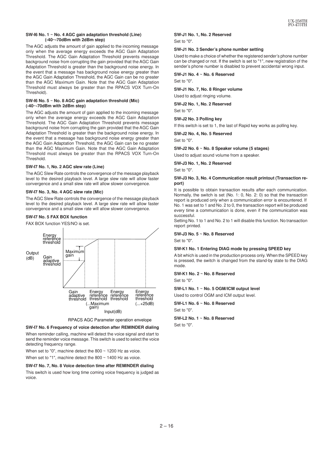
| Energy |
| |
| reference |
| |
| threshold |
| |
Output |
| Maximum | |
Gain | gain | ||
(dB) | |||
| |||
| adaptive |
| |
| threshold |
|
Gain | Energy | Energy | Energy |
adaptive | reference | reference | reference |
threshold | threshold | threshold | threshold |
(...Maximum |
| (...+25dB) | |
| gain) |
|
|
Input(dB)
RPACS AGC Parameter operation envelope
When reminder calling, machine will detect the voice signal and start to send the reminder voice message. This switch is used to select the voice detecting frequency range.
When set to "0", machine detect the 800 ~ 1200 Hz as voice.
When set to "1", machine detect the 800 ~ 1400 Hz as voice.
SW-I7 No. 7, No. 8 Voice detection time after REMINDER dialing
This switch is used how long time coming voice frequency is judged as voice.
SW-J1 No. 1, No. 2 Reserved
Set to "0".
SW-J1 No. 3 Sender’s phone number setting
Used to make a choice of whether the registered sender’s phone number can be changed or not. If the switch is set to "1", new registration of the sender’s phone number is disabled to prevent accidental wrong input.
SW-J1 No. 4 ~ No. 6 Reserved
Set to "0".
SW-J1 No. 7, No. 8 Ringer volume
Used to adjust ringing volume.
SW-J2 No. 1, No. 2 Reserved
Set to "0".
SW-J2 No. 3 Polling key
If this switch is set to 1, the last of Rapid key works as polling key.
Set to "0".
SW-J2 No. 6 ~ No. 8 Speaker volume (5 stages)
Used to adjust sound volume from a speaker.
SW-J3 No. 1, No. 2 Reserved
Set to "0".
It is possible to obtain transaction results after each communication. Normally, the switch is set (No. 1: 0, No. 2: 0) so that the transaction report is produced only when a communication error is encountered. If No. 1 was set to 1 and No. 2 to 0, the transaction report will be produced every time a communication is done, even if the communication was successful.
Setting No. 1 to 1 and No. 2 to 1 will disable this function. No transaction report printed.
SW-J3 No. 5 ~ No. 8 Reserved
Set to "0".
SW-K1 No. 1 Entering DIAG mode by pressing SPEED key
A bit which is used in the production process only. When the SPEED key is pressed, the switch is changed from the
SW-K1 No. 2 ~ No. 8 Reserved
Set to "0".
SW-L1 No. 1 ~ No. 5 OGM/ICM output level
Used to control OGM and ICM output level.
SW-L1 No. 6 ~ No. 8 Reserved
Set to "0".
SW-L2 No. 1 ~ No. 8 Reserved
Set to "0".
2 – 16