3
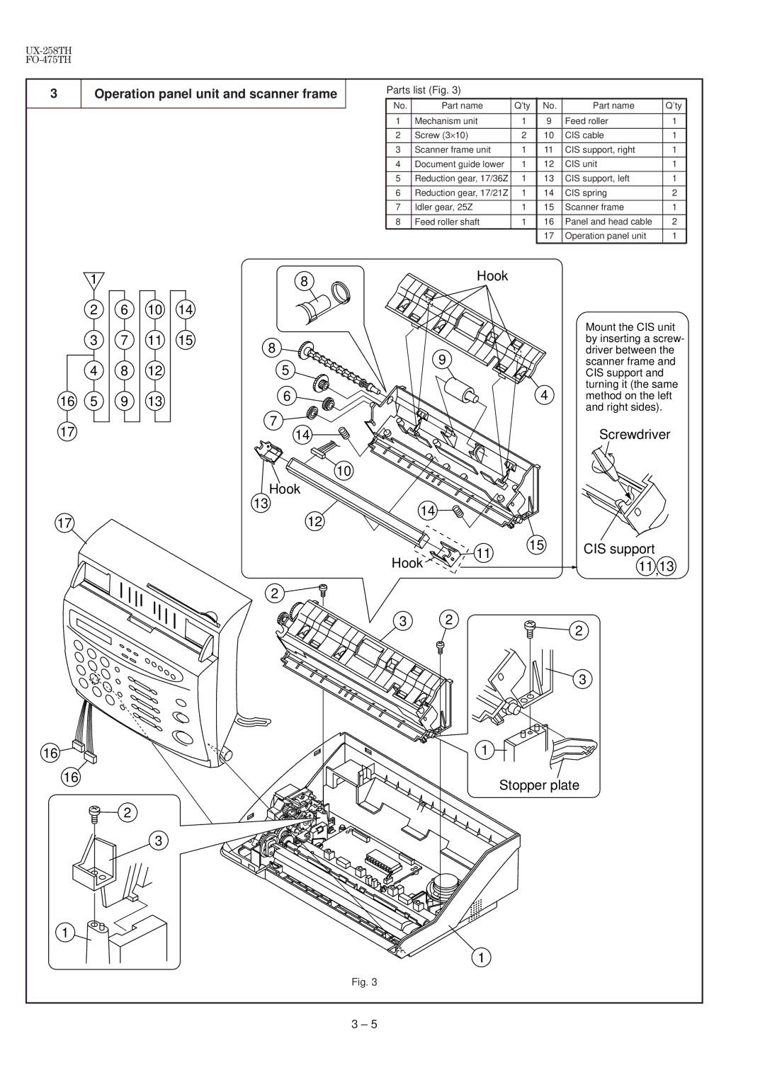
Operation panel unit and scanner frame
Parts list (Fig. 3)
No. | Part name | Q’ty | No. | Part name | Q’ty |
|
|
|
|
|
|
1 | Mechanism unit | 1 | 9 | Feed roller | 1 |
|
|
|
|
|
|
2 | Screw (3×10) | 2 | 10 | CIS cable | 1 |
|
|
|
|
|
|
3 | Scanner frame unit | 1 | 11 | CIS support, right | 1 |
|
|
|
|
|
|
4 | Document guide lower | 1 | 12 | CIS unit | 1 |
|
|
|
|
|
|
5 | Reduction gear, 17/36Z | 1 | 13 | CIS support, left | 1 |
|
|
|
|
|
|
6 | Reduction gear, 17/21Z | 1 | 14 | CIS spring | 2 |
|
|
|
|
|
|
7 | Idler gear, 25Z | 1 | 15 | Scanner frame | 1 |
|
|
|
|
|
|
8 | Feed roller shaft | 1 | 16 | Panel and head cable | 2 |
|
|
| 17 | Operation panel unit | 1 |
|
|
|
|
|
|
1
2
3
4
165
6
7
8
9
1014
1115
8 | Hook |
|
8
9
5
6 | 4 |
7
14
10
Hook
13
14
Mount the CIS unit by inserting a screw- driver between the scanner frame and CIS support and turning it (the same method on the left and right sides).
Screwdriver
17
16 |
12
11
Hook
2
3 2
1
15
CIS support 11 ,13
2
3
16 |
1
2
3
Stopper plate
1
Fig. 3
3 – 5
