CHAPTER 5. CIRCUIT DESCRIPTION
[1] Circuit description
1. General description
The compact design of the control PWB is obtained by using ROCK- WELL fax engine in the main control section and high density printing of surface mounting parts. Each PWB is independent according to its func- tion as shown in Fig. 1.
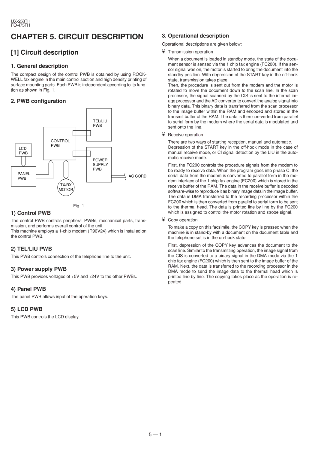
2. PWB configuration
TEL/LIU
PWB
CONTROL
PWB
LCD
PWB
POWER
SUPPLY
PWB
PANEL
3. Operational description
Operational descriptions are given below:
• | Transmission operation |
| When a document is loaded in standby mode, the state of the docu- |
| ment sensor is sensed via the 1 chip fax engine (FC200). If the sen- |
| sor signal was on, the motor is started to bring the document into the |
| standby position. With depression of the START key in the |
| state, transmission takes place. |
| Then, the procedure is sent out from the modem and the motor is |
| rotated to move the document down to the scan line. In the scan |
| processor, the signal scanned by the CIS is sent to the internal im- |
| age processor and the AD converter to convert the analog signal into |
| binary data. This binary data is transferred from the scan processor |
| to the image buffer within the RAM and encoded and stored in the |
| transmit buffer of the RAM. The data is then |
| to serial form by the modem where the serial data is modulated and |
| sent onto the line. |
• | Receive operation |
| There are two ways of starting reception, manual and automatic. |
| Depression of the START key in the |
| manual receive mode, or CI signal detection by the LIU in the auto- |
| matic receive mode. |
| First, the FC200 controls the procedure signals from the modem to |
| be ready to receive data. When the program goes into phase C, the |
PWB
AC CORD
serial data from the modem is converted to parallel form in the mo- |
dem interface of the 1 chip fax engine (FC200) which is stored in the |
TX/RX
MOTOR
Fig. 1
1) Control PWB
The control PWB controls peripheral PWBs, mechanical parts, trans- mission, and performs overall control of the unit.
This machine employs a
2) TEL/LIU PWB
This PWB controls connection of the telephone line to the unit.
3) Power supply PWB
This PWB provides voltages of +5V and +24V to the other PWBs.
4) Panel PWB
The panel PWB allows input of the operation keys.
5) LCD PWB
This PWB controls the LCD display.
receive buffer of the RAM. The data in the receive buffer is decoded |
The data is DMA transferred to the recording processor within the |
FC200 which is then converted from parallel to serial form to be sent |
to the thermal head. The data is printed line by line by the FC200 |
which is assigned to control the motor rotation and strobe signal. |
• Copy operation |
To make a copy on this facsimile, the COPY key is pressed when the |
machine is in |
the telephone set is in the |
First, depression of the COPY key advances the document to the |
scan line. Similar to the transmitting operation, the image signal from |
the CIS is converted to a binary signal in the DMA mode via the 1 |
chip fax engine (FC200) which is then sent to the image buffer of the |
RAM. Next, the data is transferred to the recording processor in the |
DMA mode to send the image data to the thermal head which is |
printed line by line. The copying takes place as the operation is re- |
peated. |
5 – 1