17 Options


 17.1
17.1 RS-232C / Relay output / Buzzer (OP-03)
Replacing
The following option cables can be used, when you do not use the relay output.
Pin connections
| Pin No. | Signal name | Direction | Description |
| 1 | HI | Output | Relay output of HI |
| 2 | RXD | Input | Receive data |
| 3 | TXD | Output | Transmit data |
| 4 | LO | Output | Relay output of LO |
| 5 | SG | - | Signal ground |
| 6 | OK | Output | Relay output of OK |
| 7 | DSR | Output | Data set ready |
| 8 | COM | - | Relay common terminal |
|
|
| ||
Mating connector | DIN 8pin, JA:TCS0586 (of accessory pack) | |||
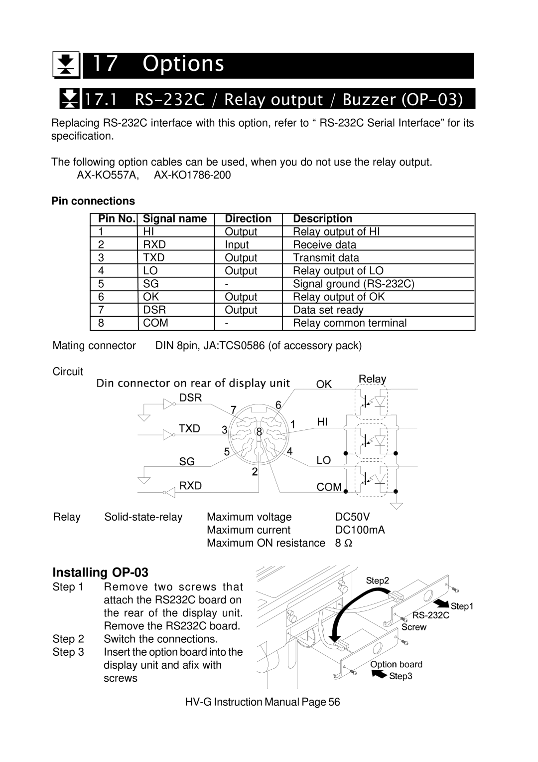
Circuit
Relay | Maximum voltage | DC50V | |
|
| Maximum current | DC100mA |
|
| Maximum ON resistance | 8 Ω |
Installing OP-03
Step 1 Remove two screws that attach the RS232C board on the rear of the display unit. Remove the RS232C board.
Step 2 Switch the connections. Step 3 Insert the option board into the
display unit and afix with screws