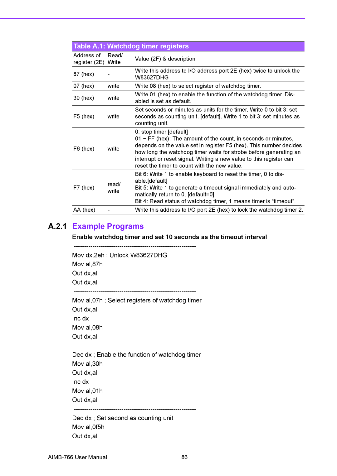
Table A.1: Watchdog timer registers
Address of | Read/ | Value (2F) & description | |
register (2E) | Write | ||
| |||
87 (hex) | - | Write this address to I/O address port 2E (hex) twice to unlock the | |
W83627DHG | |||
|
| ||
07 (hex) | write | Write 08 (hex) to select register of watchdog timer. | |
30 (hex) | write | Write 01 (hex) to enable the function of the watchdog timer. Dis- | |
abled is set as default. | |||
|
| ||
|
| Set seconds or minutes as units for the timer. Write 0 to bit 3: set | |
F5 (hex) | write | seconds as counting unit. [default]. Write 1 to bit 3: set minutes as | |
|
| counting unit. | |
|
| 0: stop timer [default] | |
|
| 01 ~ FF (hex): The amount of the count, in seconds or minutes, | |
F6 (hex) | write | depends on the value set in register F5 (hex). This number decides | |
how long the watchdog timer waits for strobe before generating an | |||
|
| ||
|
| interrupt or reset signal. Writing a new value to this register can | |
|
| reset the timer to count with the new value. | |
|
| Bit 6: Write 1 to enable keyboard to reset the timer, 0 to dis- | |
| read/ | able.[default] | |
F7 (hex) | Bit 5: Write 1 to generate a timeout signal immediately and auto- | ||
write | |||
| matically return to 0. [default=0] | ||
|
| ||
|
| Bit 4: Read status of watchdog timer, 1 means timer is “timeout”. | |
AA (hex) | - | Write this address to I/O port 2E (hex) to lock the watchdog timer 2. |
A.2.1 Example Programs
Enable watchdog timer and set 10 seconds as the timeout interval
Mov dx,2eh ; Unlock W83627DHG Mov al,87h
Out dx,al Out dx,al
Mov al,07h ; Select registers of watchdog timer Out dx,al
Inc dx Mov al,08h Out dx,al
Dec dx ; Enable the function of watchdog timer Mov al,30h
Out dx,al Inc dx Mov al,01h Out dx,al
Dec dx ; Set second as counting unit Mov al,0f5h
Out dx,al
86 |