This chapter explains the setup procedures of the
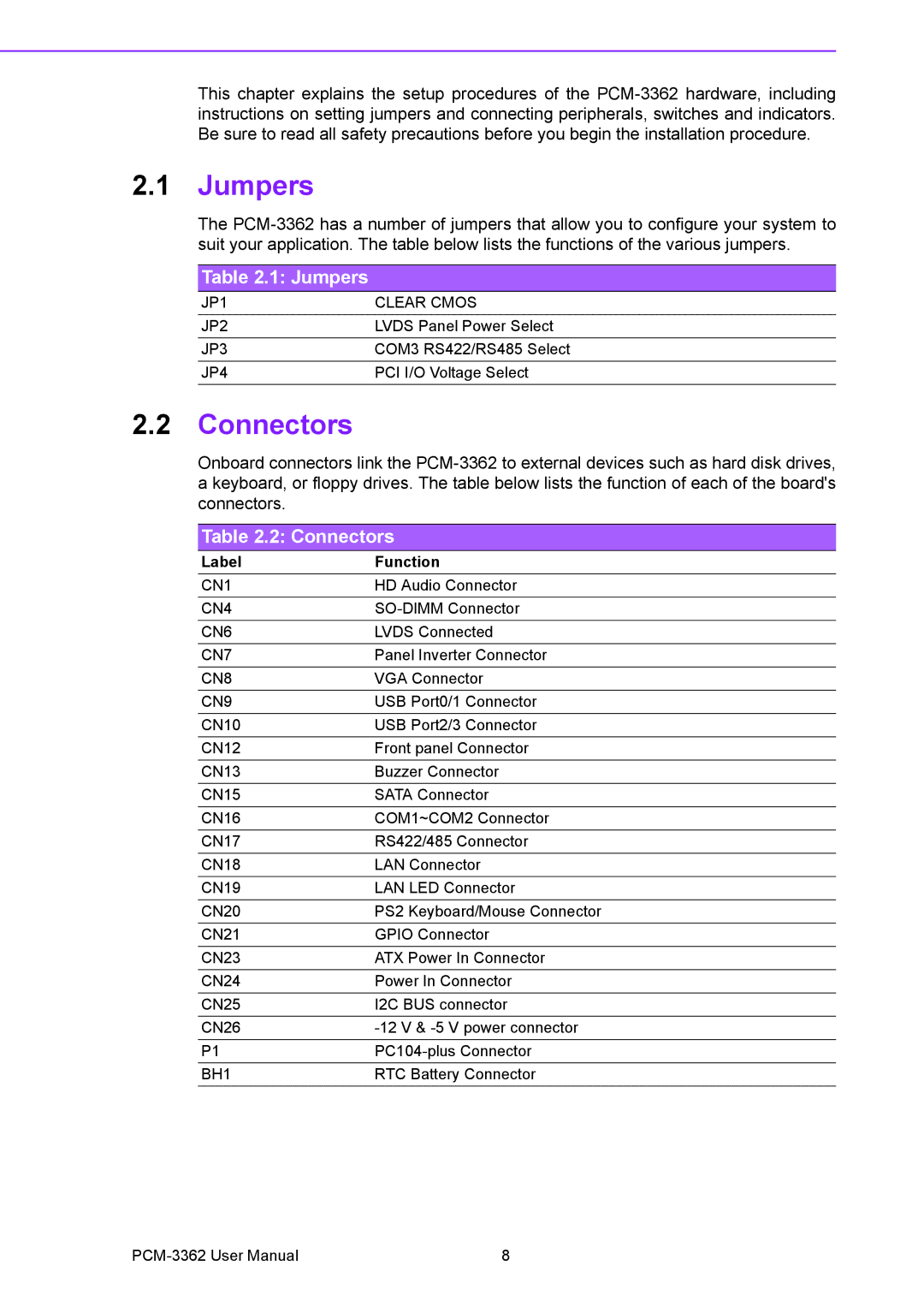
2.1Jumpers
The
Table 2.1: Jumpers
JP1 | CLEAR CMOS |
JP2 | LVDS Panel Power Select |
JP3 | COM3 RS422/RS485 Select |
JP4 | PCI I/O Voltage Select |
2.2Connectors
Onboard connectors link the
Table 2.2: Connectors
Label | Function |
CN1 | HD Audio Connector |
CN4 | |
CN6 | LVDS Connected |
CN7 | Panel Inverter Connector |
CN8 | VGA Connector |
CN9 | USB Port0/1 Connector |
CN10 | USB Port2/3 Connector |
CN12 | Front panel Connector |
CN13 | Buzzer Connector |
CN15 | SATA Connector |
CN16 | COM1~COM2 Connector |
CN17 | RS422/485 Connector |
CN18 | LAN Connector |
CN19 | LAN LED Connector |
CN20 | PS2 Keyboard/Mouse Connector |
CN21 | GPIO Connector |
CN23 | ATX Power In Connector |
CN24 | Power In Connector |
CN25 | I2C BUS connector |
CN26 | |
P1 | |
BH1 | RTC Battery Connector |
8 |