Rear Panel Switches
The
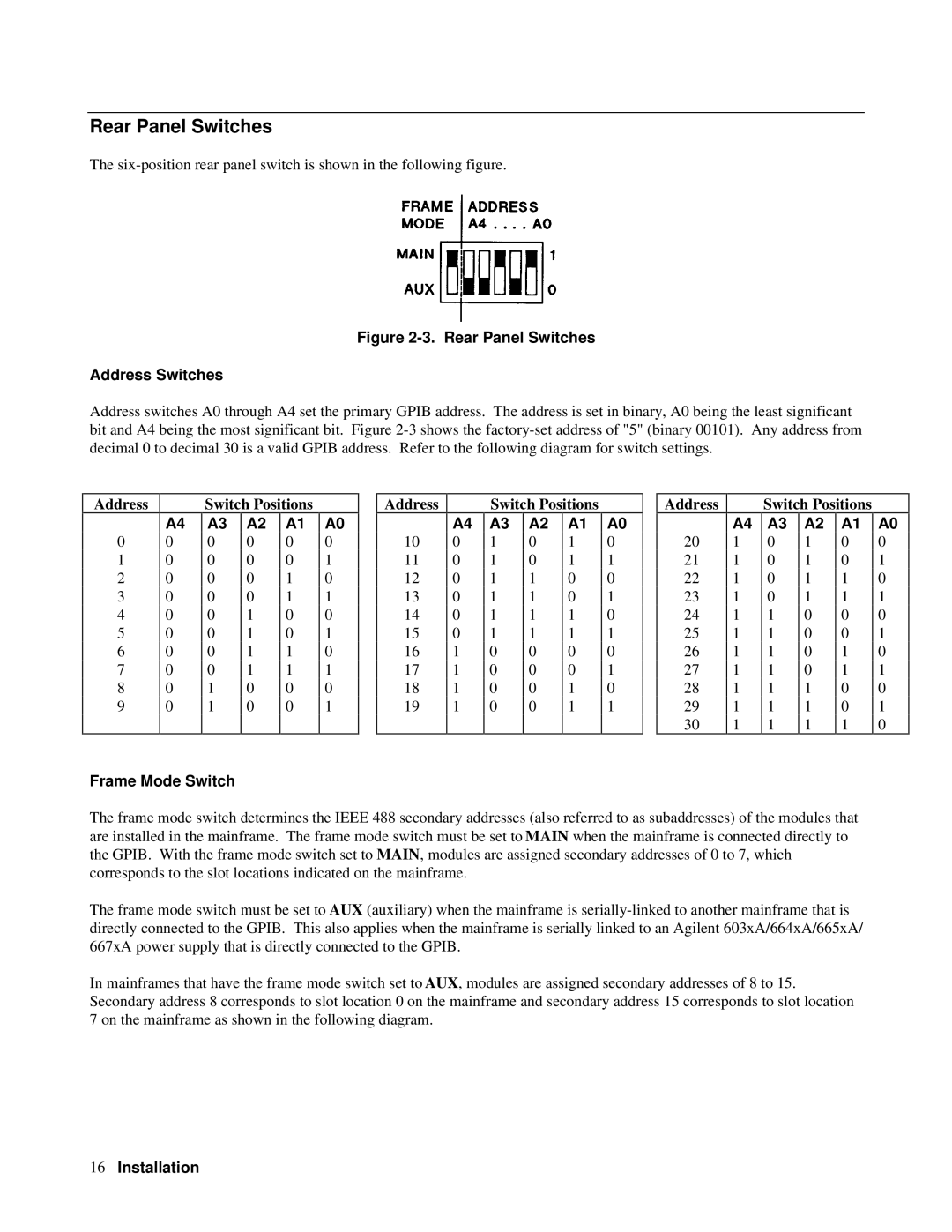
Figure 2-3. Rear Panel Switches
Address Switches
Address switches A0 through A4 set the primary GPIB address. The address is set in binary, A0 being the least significant bit and A4 being the most significant bit. Figure
Address
0
1
2
3
4
5
6
7
8
9
A4
0
0
0
0
0
0
0
0
0
0
Switch Positions
A3 | A2 | A1 |
0 | 0 | 0 |
0 | 0 | 0 |
0 | 0 | 1 |
0 | 0 | 1 |
0 | 1 | 0 |
0 | 1 | 0 |
0 | 1 | 1 |
0 | 1 | 1 |
1 | 0 | 0 |
1 | 0 | 0 |
|
|
|
A0
0
1
0
1
0
1
0
1
0
1
Address
10
11
12
13
14
15
16
17
18
19
A4
0
0
0
0
0
0
1
1
1
1
Switch Positions
A3 | A2 | A1 |
1 | 0 | 1 |
1 | 0 | 1 |
1 | 1 | 0 |
1 | 1 | 0 |
1 | 1 | 1 |
1 | 1 | 1 |
0 | 0 | 0 |
0 | 0 | 0 |
0 | 0 | 1 |
0 | 0 | 1 |
|
|
|
A0
0
1
0
1
0
1
0
1
0
1
Address
20
21
22
23
24
25
26
27
28
29
30
A4
1
1
1
1
1
1
1
1
1
1
1
Switch Positions
A3 | A2 | A1 |
0 | 1 | 0 |
0 | 1 | 0 |
0 | 1 | 1 |
0 | 1 | 1 |
1 | 0 | 0 |
1 | 0 | 0 |
1 | 0 | 1 |
1 | 0 | 1 |
1 | 1 | 0 |
1 | 1 | 0 |
1 | 1 | 1 |
A0
0
1
0
1
0
1
0
1
0
1
0
Frame Mode Switch
The frame mode switch determines the IEEE 488 secondary addresses (also referred to as subaddresses) of the modules that are installed in the mainframe. The frame mode switch must be set to MAIN when the mainframe is connected directly to the GPIB. With the frame mode switch set to MAIN, modules are assigned secondary addresses of 0 to 7, which corresponds to the slot locations indicated on the mainframe.
The frame mode switch must be set to AUX (auxiliary) when the mainframe is
In mainframes that have the frame mode switch set to AUX, modules are assigned secondary addresses of 8 to 15. Secondary address 8 corresponds to slot location 0 on the mainframe and secondary address 15 corresponds to slot location 7 on the mainframe as shown in the following diagram.
16Installation