Setting Voltage and Current. Turn the slave unit's CURRENT control fully clockwise. Adjust the master unit's controls to set the desired output voltage and current. The master supply operates in a completely normal fashion and may be set up for either con- stant voltage or constant current operation as required. Verify that the slave is in CV operation.

For auto-parallel operation of two supplies, the combined output voltage is the same as the master unit's voltage setting, and the combined output current is two times the master unit's current. In general, for two supplies, the auto-parallel output current(Io) is

Io = Im + Is = 2Im

where Im = master unit's output current Is = slave unit's output current

Proportional currents from auto-paralleled units require equal load-lead voltage drops. Connect each supply to the load using separate pairs of wire with length chosen to provide equal voltage drops from pair to pair. If this is not feasible, connect each supply to a pair of distribution terminals using equal- voltage-drop wire pairs, and then connect the distribution terminals to the load with a single pair of leads.

MASTER POWER SUPPLY


MASTER


LOCAL


+

_


+

_

+

_


M/S 1

M/S 2

CV

CC

SENSE

+S


OUT

-S

CV


CC VREF A1 A2

A3

A4 A5

SLAVE


REMOTE


LOAD


SLAVE POWER SUPPLY


MASTER


LOCAL


+

_


+

_

+

_


M/S 1

M/S 2

CV

CC

SENSE

+S


OUT

-S

CV


CC VREF A1 A2

A3

A4 A5

SLAVE


REMOTE


Figure 9. Auto-Parallel Operation of Two Supplies

Overvoltage Protection. Adjust the desired OVP shutdown limit using the master unit's OVP Adjust control. Set the slave units' OVP limits above the master's. When a master-unit shuts down, the master programs the slave units to zero voltage output. If a slave unit shuts down, it shuts only itself down. If the required cur- rent is great enough, the master will switch from CV to CC opera- tion.

Remote Sensing. To remote sense with auto-parallel operation, connect remote-sense leads only to the master unit according to the remote-sensing instructions.

Remote Analog Voltage Programming. To remote program with auto-parallel operation, set up only the master unit for remote pro-

gramming according to the remote-programming instructions.

MASTER POWER SUPPLY


_


_

+ _


MASTER


LOCAL


+


+


M/S 1 M/S 2

CV

CC

SENSE

+S

OUT


-S

CV


CC VREF A1 A2

A3

A4

A5

SLAVE


REMOTE


LOAD


SLAVE POWER SUPPLY


_


_

+ _


MASTER


LOCAL


+


+


M/S 1 M/S 2

CV

CC

SENSE

+S

OUT


-S

CV


CC VREF A1 A2

A3

A4

A5

SLAVE


REMOTE


SLAVE POWER SUPPLY


_


_

+ _


MASTER


LOCAL


+


+


M/S 1 M/S 2

CV

CC

SENSE

+S

OUT


-S

CV


CC VREF A1 A2

A3

A4

A5

SLAVE


REMOTE


Figure 10. Auto-Parallel Operation of Three Supplies

NORMAL SERIES OPERATION

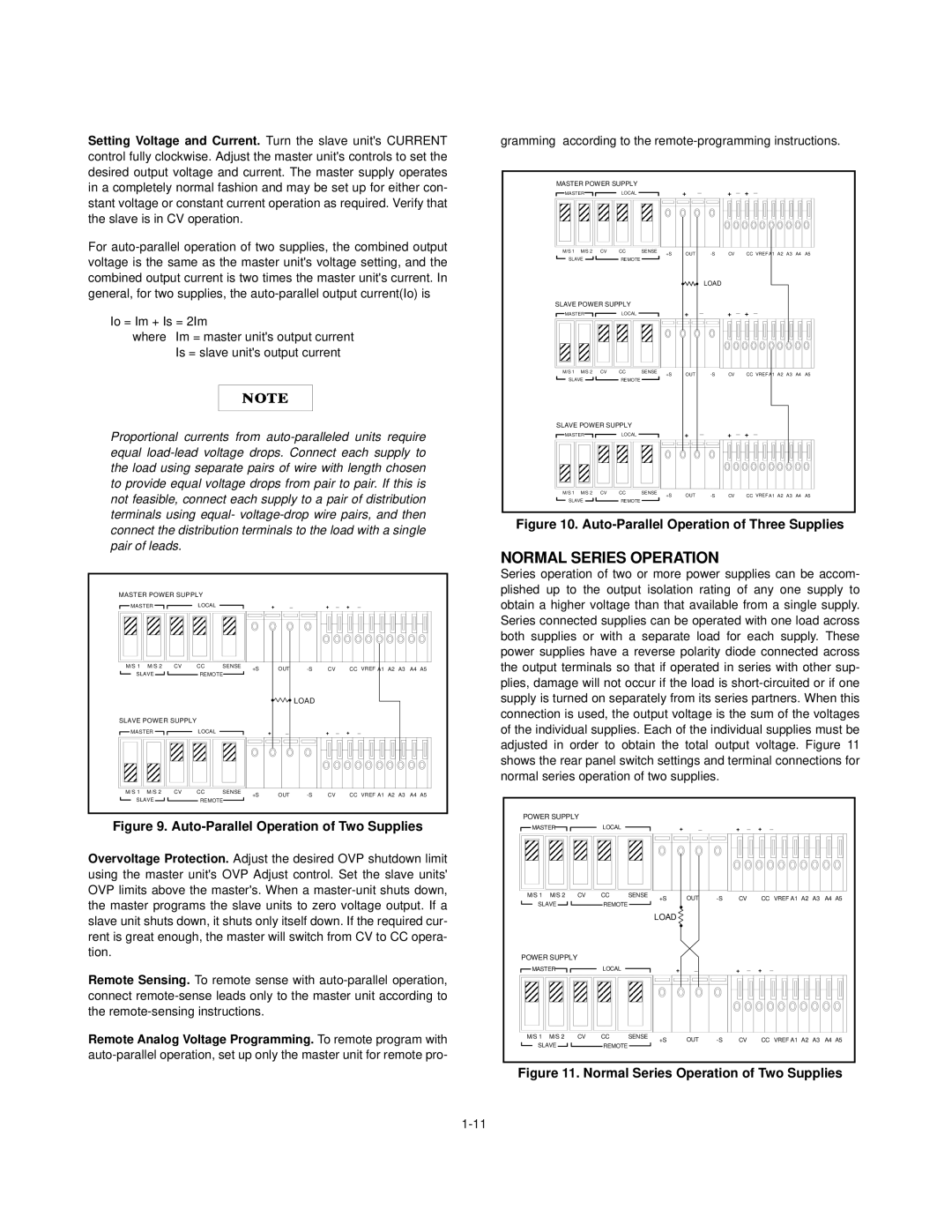
Series operation of two or more power supplies can be accom- plished up to the output isolation rating of any one supply to obtain a higher voltage than that available from a single supply. Series connected supplies can be operated with one load across both supplies or with a separate load for each supply. These power supplies have a reverse polarity diode connected across the output terminals so that if operated in series with other sup- plies, damage will not occur if the load is short-circuited or if one supply is turned on separately from its series partners. When this connection is used, the output voltage is the sum of the voltages of the individual supplies. Each of the individual supplies must be adjusted in order to obtain the total output voltage. Figure 11 shows the rear panel switch settings and terminal connections for normal series operation of two supplies.

POWER SUPPLY


MASTER


LOCAL


+

_


+

_

+

_


M/S 1

M/S 2

CV

CC

SENSE

+S

OUT

-S

CV


CC

VREF A1 A2 A3

A4 A5

SLAVE


REMOTE


LOAD


POWER SUPPLY


MASTER


LOCAL


+

_


+

_

+

_


M/S 1

M/S 2

CV

CC

SENSE

+S

OUT

-S

CV


CC

VREF A1 A2 A3

A4 A5

SLAVE


REMOTE


Figure 11. Normal Series Operation of Two Supplies

1-11

Page 11
Image 11
Agilent Technologies Agilent E3614A Serials KR83503035, Agilent E3616A Serials KR83502651 Normal Series Operation

Agilent E3614A Serials KR83503035, Agilent E3617A Serials KR83502522, Agilent E3615A Serials KR83506197, Agilent E3616A Serials KR83502651 specifications

Agilent Technologies is a leading player in the field of electronic test and measurement devices, providing essential tools for engineers and scientists. Among their array of power supplies, models such as the Agilent E3616A, E3615A, E3617A, and E3614A stand out for their exceptional performance, reliability, and technological features.

The Agilent E3616A is a precision DC power supply known for its ability to deliver a maximum output of 60V and 3A. Its serial number, KR83502651, signifies its unique identity. This model is particularly valued in laboratory environments due to its advanced programming capabilities. It offers a comprehensive range of output voltage and current settings, making it versatile for various applications. One of its main features is the built-in 6V at 3A output, which can be useful for testing other devices.

Similarly, the Agilent E3615A, with the serial number KR83506197, provides an excellent blend of performance and functionality. It is capable of delivering up to 30V and 3A across its outputs. This model excels in its low noise operation, which is crucial for sensitive electronics testing. Furthermore, the user-friendly interface allows for quick adjustments and settings retrieval, making it a favorite among engineers. The E3615A is designed to support a wide range of applications, from component testing to powering devices in research settings.

The Agilent E3617A, identifiable by its serial number KR83502522, is another high-performance model that offers a maximum output of 30V and up to 3A. It features built-in read-back capabilities, enabling engineers to monitor the actual voltage and current supplied to the load. The E3617A stands out for its programmable output, allowing automated testing sequences to be implemented with ease.

Lastly, the Agilent E3614A, with the serial number KR83503035, is a cost-effective option without sacrificing quality. This model offers an output of up to 30V and 3A while maintaining stability and precision. Its compact design makes it easy to integrate into crowded workspaces or test setups. The E3614A is designed for durability, ensuring reliable performance over time, making it an excellent choice for both education and industrial applications.

With their high-precision outputs, easy programmability, and user-friendly interfaces, these Agilent power supplies serve as essential tools for a variety of testing and research needs, reflecting Agilent Technologies' commitment to quality and innovation in electronic measurement solutions.