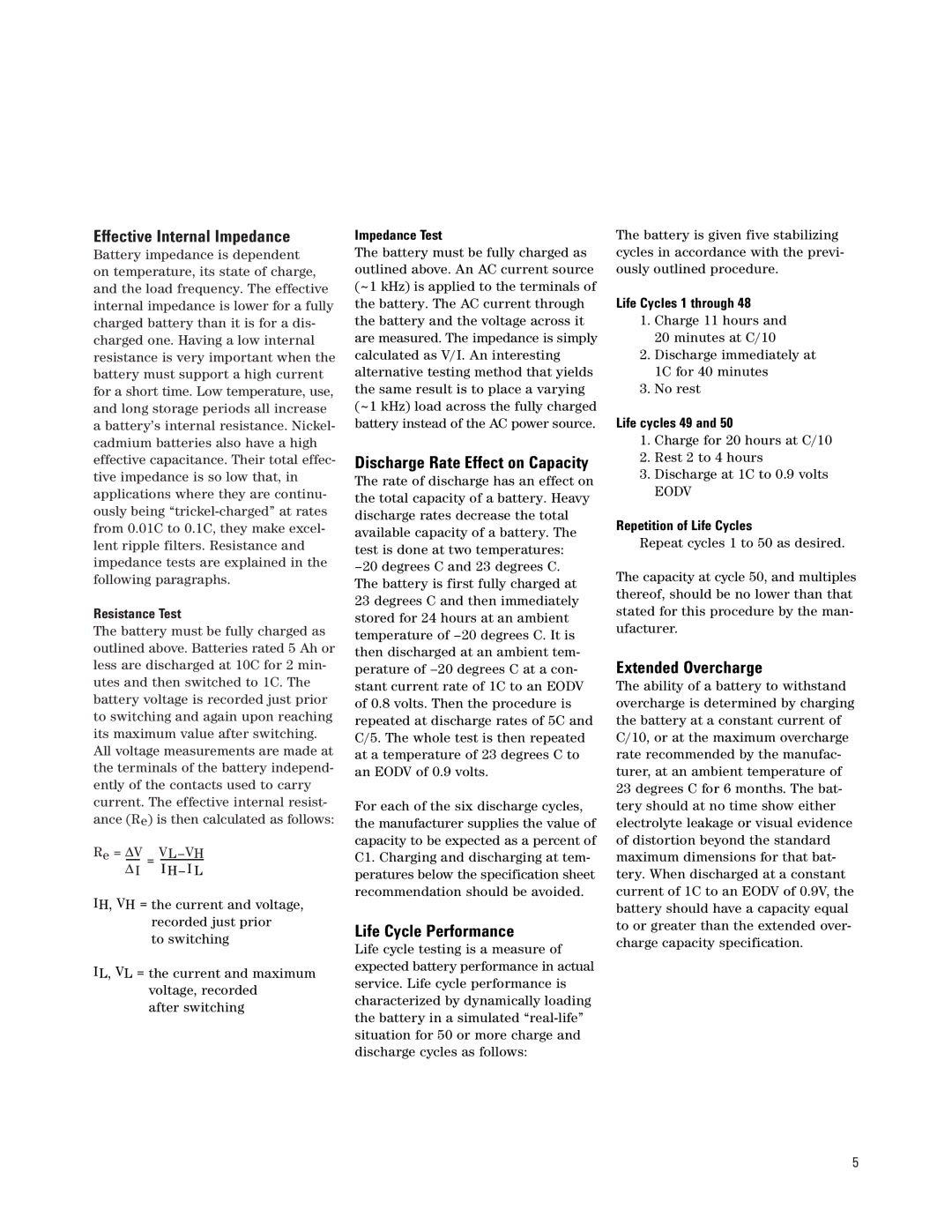
Effective Internal Impedance
Battery impedance is dependent on temperature, its state of charge, and the load frequency. The effective internal impedance is lower for a fully charged battery than it is for a dis- charged one. Having a low internal resistance is very important when the battery must support a high current for a short time. Low temperature, use, and long storage periods all increase a battery’s internal resistance. Nickel- cadmium batteries also have a high effective capacitance. Their total effec- tive impedance is so low that, in applications where they are continu- ously being
Resistance Test
The battery must be fully charged as outlined above. Batteries rated 5 Ah or less are discharged at 10C for 2 min- utes and then switched to 1C. The battery voltage is recorded just prior to switching and again upon reaching its maximum value after switching. All voltage measurements are made at the terminals of the battery independ- ently of the contacts used to carry current. The effective internal resist- ance (Re) is then calculated as follows:
Re = | Δ V |
|
| |
|
| = |
| I H– I L |
Δ I = |
| |||
IH, VH = the current and voltage, recorded just prior
to switching
IL, VL = the current and maximum voltage, recorded
after switching
Impedance Test
The battery must be fully charged as outlined above. An AC current source (~1 kHz) is applied to the terminals of the battery. The AC current through the battery and the voltage across it are measured. The impedance is simply calculated as V/I. An interesting alternative testing method that yields the same result is to place a varying (~1 kHz) load across the fully charged battery instead of the AC power source.
Discharge Rate Effect on Capacity
The rate of discharge has an effect on the total capacity of a battery. Heavy discharge rates decrease the total available capacity of a battery. The test is done at two temperatures:
For each of the six discharge cycles, the manufacturer supplies the value of capacity to be expected as a percent of C1. Charging and discharging at tem- peratures below the specification sheet recommendation should be avoided.
Life Cycle Performance
Life cycle testing is a measure of expected battery performance in actual service. Life cycle performance is characterized by dynamically loading the battery in a simulated
The battery is given five stabilizing cycles in accordance with the previ- ously outlined procedure.
Life Cycles 1 through 48
1.Charge 11 hours and 20 minutes at C/10
2.Discharge immediately at 1C for 40 minutes
3.No rest
Life cycles 49 and 50
1.Charge for 20 hours at C/10
2.Rest 2 to 4 hours
3.Discharge at 1C to 0.9 volts
EODV
Repetition of Life Cycles
Repeat cycles 1 to 50 as desired.
The capacity at cycle 50, and multiples thereof, should be no lower than that stated for this procedure by the man- ufacturer.
Extended Overcharge
The ability of a battery to withstand overcharge is determined by charging the battery at a constant current of C/10, or at the maximum overcharge rate recommended by the manufac- turer, at an ambient temperature of 23 degrees C for 6 months. The bat- tery should at no time show either electrolyte leakage or visual evidence of distortion beyond the standard maximum dimensions for that bat- tery. When discharged at a constant current of 1C to an EODV of 0.9V, the battery should have a capacity equal to or greater than the extended over- charge capacity specification.
5
