83873900 0602 E specifications
The Aiphone 83873900 0602 E is a sophisticated intercom system designed to enhance communication and security in residential and commercial environments. This model combines advanced technologies and user-friendly features, making it an ideal choice for those seeking reliable intercom solutions.One of the main features of the Aiphone 83873900 0602 E is its dual-channel capability, allowing users to communicate over two separate lines. This feature is particularly useful in larger homes or office complexes where managing multiple conversations is essential. The intercom system is equipped with clear audio output, ensuring that conversations are crisp and easy to understand, even in noisy environments.
A key characteristic of the Aiphone 83873900 0602 E is its robust build quality. Constructed with durable materials, this intercom can withstand the rigors of daily use while providing a sleek and modern aesthetic. The design ensures that it blends seamlessly into a variety of settings, whether placed in a home, a retail space, or an office.
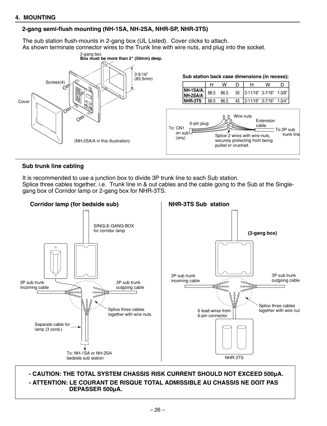
Technologically, the Aiphone 83873900 0602 E employs innovative digital signal processing which enhances audio clarity and minimizes background noise during conversations. It also features a user-friendly interface with intuitive controls, making it simple for users of all ages to operate. The system integrates easily with existing wiring, reducing installation complexity and cost.
Another notable feature of the Aiphone 83873900 0602 E is its expandability. Users can connect multiple units together, allowing for customized setups that cater to specific needs. This scalability makes it a versatile option for both small residences and larger enterprises.
The device is also equipped with visual indicators that alert users to incoming calls, ensuring that important communications are never missed. This feature is particularly beneficial in busy environments where distractions may lead to missed messages.
In summary, the Aiphone 83873900 0602 E stands out in the intercom market with its dual-channel capability, durable construction, advanced digital technologies, and excellent expandability. Whether for personal use or a professional setting, this intercom system delivers reliable performance, modern functionality, and ease of use, making it a worthy investment for enhancing communication and security. Choosing the Aiphone 83873900 0602 E means opting for a product that embodies convenience, quality, and innovation.

