WIRING DIAGRAMS

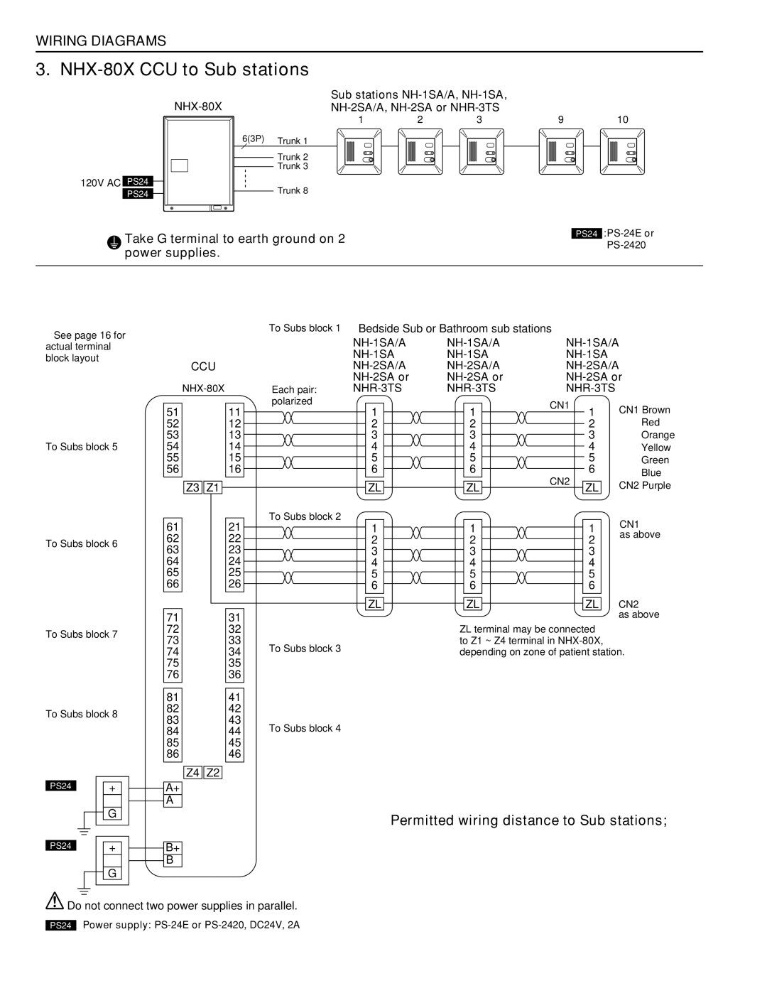
3. NHX-80X CCU to Sub stations

NHX-80X

Sub stations NH-1SA/A, NH-1SA,


NH-2SA/A, NH-2SA or NHR-3TS


1

2

3

9

10

6(3P)

Trunk 1


Trunk 2


Trunk 3


120V AC PS24

Trunk 8


PS24


Take G terminal to earth ground on 2 power supplies.

PS24 :PS-24E or PS-2420

See page 16 for


To Subs block 1 Bedside Sub or Bathroom sub stations


NH-1SA/A

NH-1SA/A

NH-1SA/A

actual terminal


NH-1SA

NH-1SA

NH-1SA


block layout


CCU


NH-2SA/A

NH-2SA/A

NH-2SA/A


NH-2SA or

NH-2SA or

NH-2SA or


NHX-80X


Each pair:

NHR-3TS

NHR-3TS

NHR-3TS


polarized


CN1


CN1 Brown


51


11


1


1


1


52


12


2


2


2


Red


53


13


3


3


3


Orange

To Subs block 5

54


14


4


4


4


Yellow


55


15


5


5


5


Green


56


16


6


6


6


Blue


CN2


CN2 Purple


Z3

Z1


ZL


ZL


ZL


To Subs block 2


CN1


61


21


1


1


1


To Subs block 6

62


22


2


2


2


as above

63


23


3


3


3


64


24


4


4


4


65


25


5


5


5


66


26


6


6


6


ZL


ZL


ZL


CN2


71


31


as above

To Subs block 7

72


32


ZL terminal may be connected


73


33


to Z1 ~ Z4 terminal in NHX-80X,


To Subs block 3


74


34


depending on zone of patient station.


75


35


76


36


Trunk line from NHX-80X to sub stations should be


81


41


Aiphone specified cable or UL Listed cable

To Subs block 8

82


42


(3 twisted pair).


83


43

To Subs block 4


84


44


85


45


• If 4-zone lamp is included, use 4 twisted pairs.


86


46


• In a zone with more than 10 stations, additional


Z4

Z2


subs must be wired in a separate trunk line, but

PS24


+


A+


the ZL line may be extended from any sub on the


A–


previous trunk line.


G


Permitted wiring distance to Sub stations;


165' with 22AWG, 50m with 0.65mm (from CCU to


PS24


+


B+


farthest sub).


B–


Max. 330', 100m total distance per trunkage line


G


(includes length of trunk line, plus wire length


T-tapped from junction point to each patient station


Do not connect two power supplies in parallel.


in the trunk line).


PS24


Power supply: PS-24E or PS-2420, DC24V, 2A


– 20 –

Page 20
Image 20
Aiphone 83873900 0602 E NHX-80X CCU to Sub stations, Permitted wiring distance to Sub stations, NH-2SA or

83873900 0602 E specifications

The Aiphone 83873900 0602 E is a sophisticated intercom system designed to enhance communication and security in residential and commercial environments. This model combines advanced technologies and user-friendly features, making it an ideal choice for those seeking reliable intercom solutions.

One of the main features of the Aiphone 83873900 0602 E is its dual-channel capability, allowing users to communicate over two separate lines. This feature is particularly useful in larger homes or office complexes where managing multiple conversations is essential. The intercom system is equipped with clear audio output, ensuring that conversations are crisp and easy to understand, even in noisy environments.

A key characteristic of the Aiphone 83873900 0602 E is its robust build quality. Constructed with durable materials, this intercom can withstand the rigors of daily use while providing a sleek and modern aesthetic. The design ensures that it blends seamlessly into a variety of settings, whether placed in a home, a retail space, or an office.

Technologically, the Aiphone 83873900 0602 E employs innovative digital signal processing which enhances audio clarity and minimizes background noise during conversations. It also features a user-friendly interface with intuitive controls, making it simple for users of all ages to operate. The system integrates easily with existing wiring, reducing installation complexity and cost.

Another notable feature of the Aiphone 83873900 0602 E is its expandability. Users can connect multiple units together, allowing for customized setups that cater to specific needs. This scalability makes it a versatile option for both small residences and larger enterprises.

The device is also equipped with visual indicators that alert users to incoming calls, ensuring that important communications are never missed. This feature is particularly beneficial in busy environments where distractions may lead to missed messages.

In summary, the Aiphone 83873900 0602 E stands out in the intercom market with its dual-channel capability, durable construction, advanced digital technologies, and excellent expandability. Whether for personal use or a professional setting, this intercom system delivers reliable performance, modern functionality, and ease of use, making it a worthy investment for enhancing communication and security. Choosing the Aiphone 83873900 0602 E means opting for a product that embodies convenience, quality, and innovation.