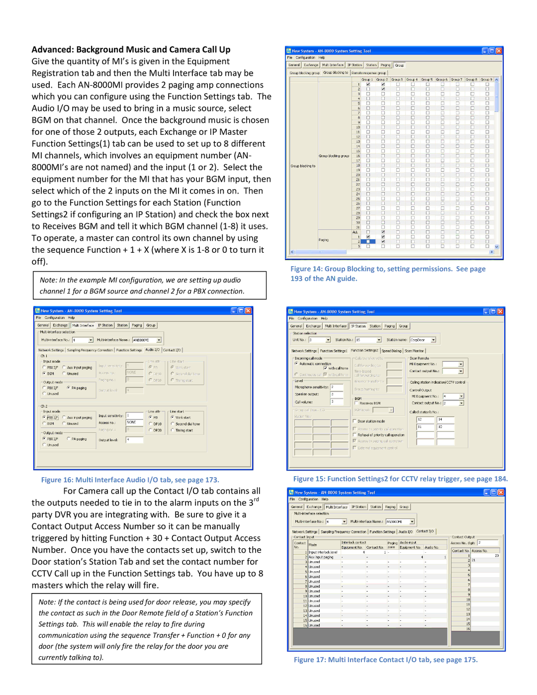
Advanced: Background Music and Camera Call Up Give the quantity of MI’s is given in the Equipment Registration tab and then the Multi Interface tab may be used. Each
Note: In the example MI configuration, we are setting up audio channel 1 for a BGM source and channel 2 for a PBX connection.
Figure 16: Multi Interface Audio I/O tab, see page 173.
For Camera call up the Contact I/O tab contains all the outputs needed to tie in to the alarm inputs on the 3rd party DVR you are integrating with. Be sure to give it a Contact Output Access Number so it can be manually triggered by hitting Function + 30 + Contact Output Access Number. Once you have the contacts set up, switch to the Door station’s Station Tab and set the contact number for CCTV Call up in the Function Settings tab. You have up to 8 masters which the relay will fire.
Note: If the contact is being used for door release, you may specify the contact as such in the Door Remote field of a Station’s Function Settings tab. This will enable the relay to fire during communication using the sequence Transfer + Function + 0 for any door (the system will only fire the relay for the door you are currently talking to).
