GH-VAX specifications
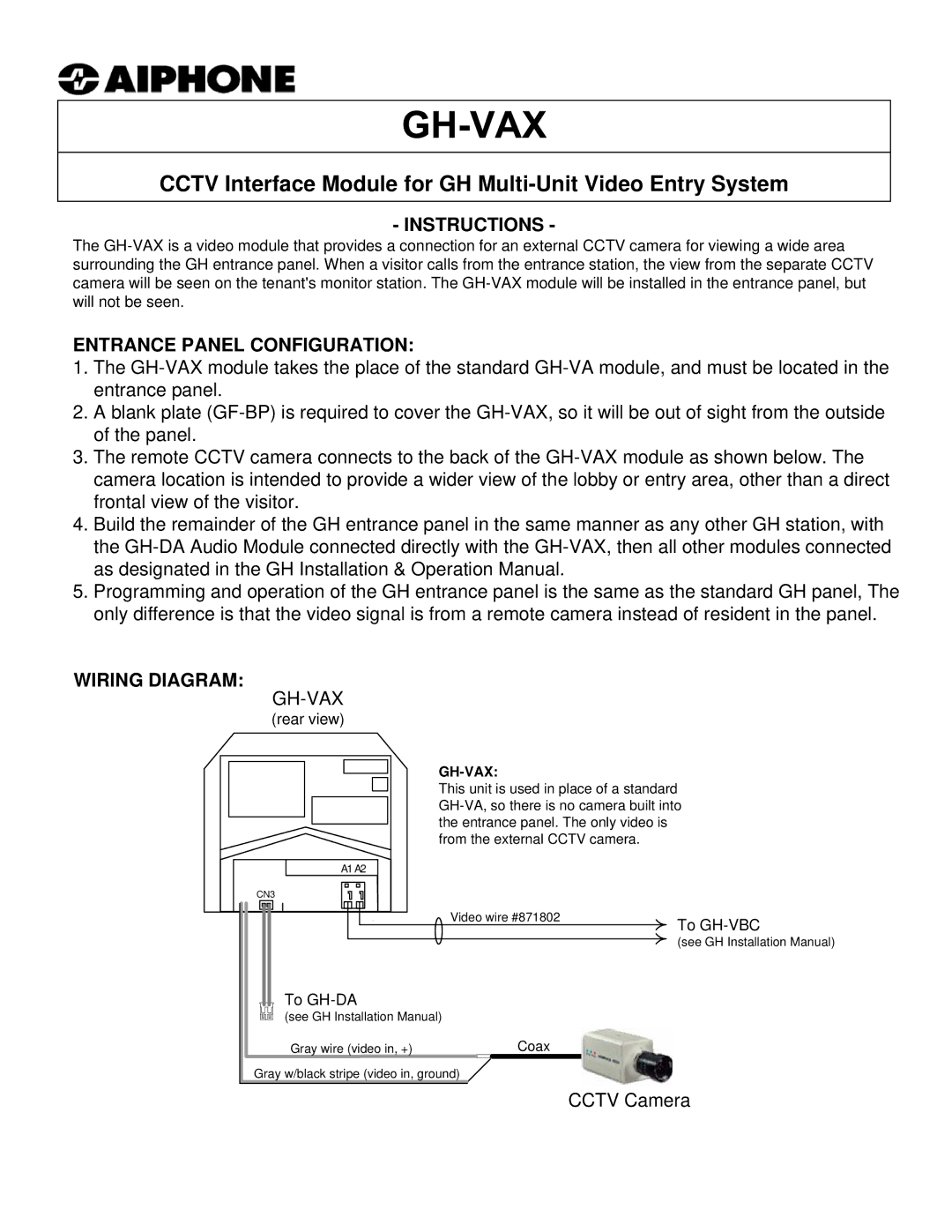
The Aiphone GH-VAX is a state-of-the-art intercom system designed to enhance communication and security in various environments such as residential buildings, commercial spaces, and institutional facilities. This advanced intercom solution simplifies interactions and provides users with a robust set of features catered to modern communication needs.One of the standout features of the GH-VAX is its high-definition video capabilities. Equipped with a camera that offers crystal-clear visuals, the system allows users to see who is at the door before granting access. The integration of a wide-angle lens ensures maximum coverage, making it difficult for anyone to go unnoticed. Coupled with infrared night vision technology, the device provides clear imagery even in low-light conditions, ensuring security at all times.
Another significant characteristic of the Aiphone GH-VAX is its innovative audio technology. The device incorporates full-duplex audio, which facilitates natural, uninterrupted conversations between users. Utilizing advanced noise cancellation and echo suppression ensures that audio transmissions are clear, maintaining effective communication even in noisy environments.
The GH-VAX is designed with user convenience in mind. The outdoor station is equipped with an easy-to-use touchscreen interface that allows users to navigate through functions intuitively. Furthermore, it supports multiple station connectivity, enabling seamless communication between various units across the facility. This feature is particularly useful in large buildings where direct communication between different areas is essential.
Integration capabilities also set the Aiphone GH-VAX apart from other intercom systems. It can be easily connected to existing security systems, including access control panels and alarm systems, enhancing overall security management. The device supports various communication protocols, ensuring compatibility with a wide range of third-party applications and devices, which makes it versatile in deployment.
Additionally, the GH-VAX has a sleek, modern design that fits discreetly into any environment while maintaining a robust build quality that ensures durability. Its weather-resistant construction makes it suitable for outdoor installations, capable of withstanding various environmental factors.
In summary, the Aiphone GH-VAX is a feature-rich intercom system that combines high-definition video, superior audio quality, user-friendly design, and robust integration capabilities, making it an ideal choice for enhancing communication and security in any setting. Its advanced technology ensures that users can manage their interactions efficiently and securely.

