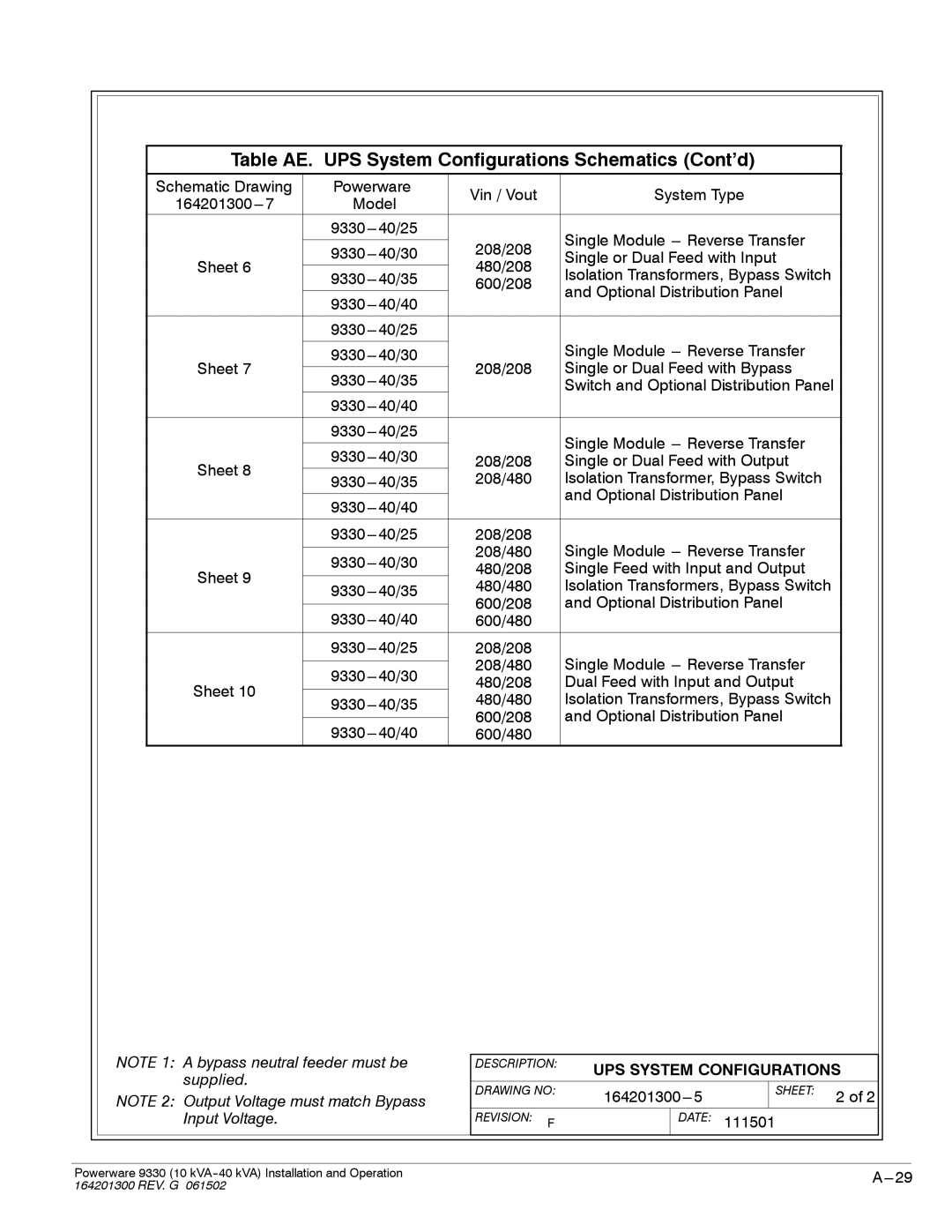
Table AE. UPS System Configurations Schematics (Cont’d)
Schematic Drawing | Powerware | Vin / Vout | System Type | |
Model | ||||
|
| |||
|
| Single Module | ||
|
| 208/208 | ||
| ||||
| Single or Dual Feed with Input | |||
Sheet 6 |
| 480/208 | Isolation Transformers, Bypass Switch | |
| 600/208 | |||
|
|
| and Optional Distribution Panel | |
|
| |||
|
|
| ||
|
|
|
| |
|
|
| ||
|
|
| Single Module | |
|
| |||
Sheet 7 |
| 208/208 | Single or Dual Feed with Bypass | |
|
| Switch and Optional Distribution Panel | ||
|
|
| ||
|
|
|
| |
|
| Single Module | ||
|
|
| ||
|
| |||
Sheet 8 | 208/208 | Single or Dual Feed with Output | ||
208/480 | Isolation Transformer, Bypass Switch | |||
| ||||
|
|
| and Optional Distribution Panel | |
|
| |||
|
|
| ||
|
|
|
| |
| 208/208 | Single Module | ||
|
| 208/480 | ||
| ||||
Sheet 9 | 480/208 | Single Feed with Input and Output | ||
| ||||
480/480 | Isolation Transformers, Bypass Switch | |||
| ||||
|
| 600/208 | and Optional Distribution Panel | |
| ||||
| 600/480 |
| ||
|
|
|
| |
| 208/208 | Single Module | ||
|
| 208/480 | ||
| ||||
Sheet 10 | 480/208 | Dual Feed with Input and Output | ||
| ||||
480/480 | Isolation Transformers, Bypass Switch | |||
| ||||
|
| 600/208 | and Optional Distribution Panel | |
| ||||
| 600/480 |
|
NOTE 1: A bypass neutral feeder must be supplied.
NOTE 2: Output Voltage must match Bypass Input Voltage.
DESCRIPTION: | UPS SYSTEM CONFIGURATIONS | ||||
| |||||
|
|
|
|
|
|
DRAWING NO: |
| SHEET: | 2 of 2 | ||
|
|
| |||
|
|
|
|
|
|
REVISION: F |
| DATE: | 111501 |
| |
Powerware 9330 (10 | |
164201300 REV. G 061502 |
|
