MAINTENANCE BYPASS MODE
|
|
| STATIC |
|
MAINTENANCE | K5 | SWITCH |
| |
BYPASS SWITCH |
|
| ||
|
| RECTIFIER | BOOST | INVERTER |
|
| CONVERTER | ||
CB1 | K1 |
| K3 | |
|
| |||
|
|
|
| MAINTENANCE |
|
|
|
| BYPASS SWITCH |
CHARGER | K2 |
Main Power Flow
Breakers Contactors |
| Trickle Current |
|
| |
Closed | CB2 |
|
| Energized | |
|
| |
Open |
|
|
|
|
BATTERY
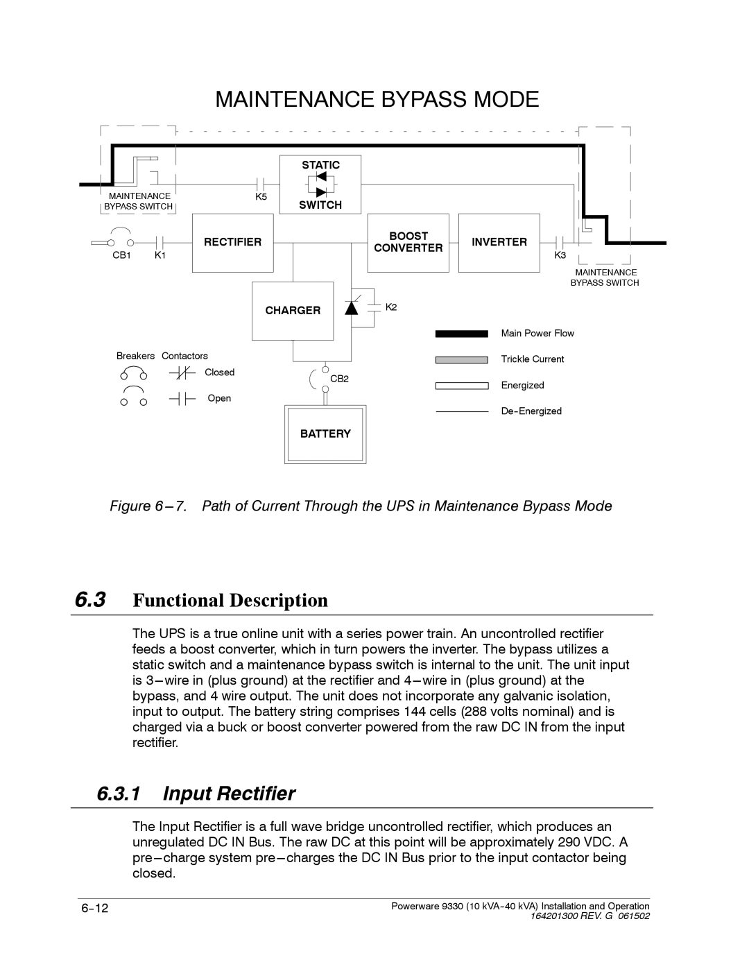
Figure 6 ---7. Path of Current Through the UPS in Maintenance Bypass Mode
6.3Functional Description
The UPS is a true online unit with a series power train. An uncontrolled rectifier feeds a boost converter, which in turn powers the inverter. The bypass utilizes a static switch and a maintenance bypass switch is internal to the unit. The unit input is
6.3.1Input Rectifier
The Input Rectifier is a full wave bridge uncontrolled rectifier, which produces an unregulated DC IN Bus. The raw DC at this point will be approximately 290 VDC. A
Powerware 9330 (10 | |
| 164201300 REV. G 061502 |