6.2.4Battery Mode
The UPS transfers to Battery mode automatically if a utility power outage occurs, or if the utility power does not conform to specified parameters. In Battery mode, the battery provides emergency DC power that the inverter converts to AC power.
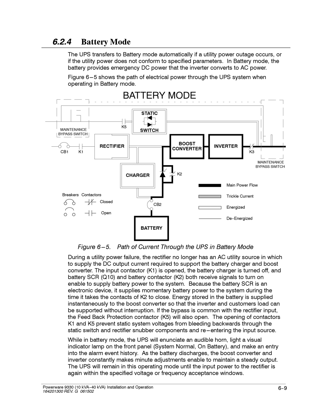
Figure 6---5 shows the path of electrical power through the UPS system when operating in Battery mode.
BATTERY MODE
|
|
| STATIC |
|
MAINTENANCE | K5 | SWITCH |
| |
|
| |||
BYPASS SWITCH |
|
|
| |
|
| RECTIFIER | BOOST | INVERTER |
|
| CONVERTER | ||
CB1 | K1 |
| K3 | |
|
| |||
|
|
|
| MAINTENANCE |
|
|
|
| BYPASS SWITCH |
CHARGER | K2 |
Main Power Flow
Breakers Contactors
Closed | CB2 |
| |
Open |
|
BATTERY
Trickle Current
Energized
Figure 6 ---5. Path of Current Through the UPS in Battery Mode
During a utility power failure, the rectifier no longer has an AC utility source in which to supply the DC output current required to support the battery charger and boost converter. The input contactor (K1) is opened, the battery charger is turned off, and battery SCR (Q10) and battery contactor (K2) both receive signals to turn on enable to supply battery power to the system. Because the battery SCR is an electronic device, it supplies momentary battery power to the system during the time it takes the contacts of K2 to close. Energy stored in the battery is supplied instantaneously to the boost converter so that the inverter and customers load can be supported without interruption. If the bypass is common with the rectifier input, the Feed Back Protection contactor (K5) will also open. The opening of contactors K1 and K5 prevent static system voltages from bleeding backwards through the static switch and rectifier snubber components and
While in battery mode, the UPS will enunciate an audible horn, light a visual indicator lamp on the front panel (System Normal, On Battery), and make an entry into the alarm event history. As the battery discharges, the boost converter and inverter constantly makes minute adjustments enable to maintain a steady output. The UPS will remain in this operating mode until the input power to the rectifier is again within the specified voltage or frequency acceptance windows.
|
|
|
Powerware 9330 (10 | ||
164201300 REV. G 061502 |
|
|