COVER
TB2 | TB1 |
BOTTOM ENCLOSURE
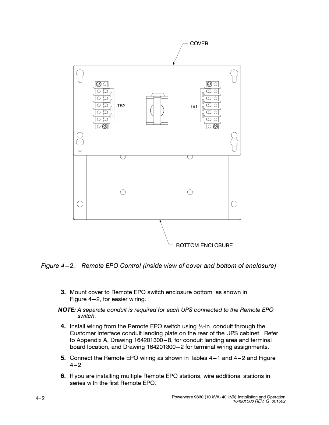
Figure 4 ---2. Remote EPO Control (inside view of cover and bottom of enclosure)
3.Mount cover to Remote EPO switch enclosure bottom, as shown in Figure
NOTE: A separate conduit is required for each UPS connected to the Remote EPO switch.
4.Install wiring from the Remote EPO switch using
5.Connect the Remote EPO wiring as shown in Tables
6.If you are installing multiple Remote EPO stations, wire additional stations in series with the first Remote EPO.
Powerware 9330 (10 | |
| 164201300 REV. G 061502 |
