6.2.5Test and Maintenance Bypass Modes
An internal maintenance switch is used to safely supply utility power to the system output during periods of maintenance or repairs. Before this switch is used, the UPS should be transferred to bypass and the Power Processing Unit (PPU) should be turned off. This switch has three positions: UPS (normal), TEST, BYPASS. The bypass source supplies the commercial AC power to the load directly.
While on internal bypass, when a user rotates the maintenance switch from the UPS position to the TEST position, the load is wrapped around the UPS, while power is still supplied to the internal bypass. The static switch remains energized to support the load should the user rotate the switch back to the UPS (normal) position. When the maintenance switch is rotated back to the UPS position from the TEST position, the load is switched back to the internal bypass. If the maintenance switch is rotated to BYPASS instead of to UPS from the TEST position, the load remains wrapped around the UPS and power is removed from the entire upper half of the unit allowing service work to be completed on the unit safely.
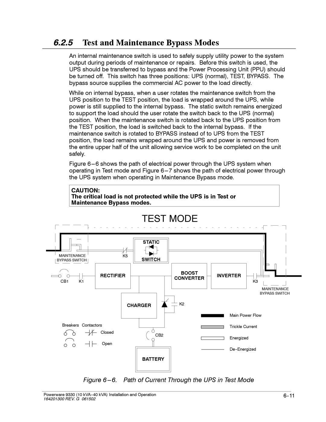
Figure 6---6 shows the path of electrical power through the UPS system when operating in Test mode and Figure 6---7 shows the path of electrical power through the UPS system when operating in Maintenance Bypass mode.
CAUTION:
The critical load is not protected while the UPS is in Test or
Maintenance Bypass modes.
TEST MODE
|
|
| STATIC |
|
MAINTENANCE | K5 | SWITCH |
| |
BYPASS SWITCH |
|
| ||
|
| RECTIFIER | BOOST | INVERTER |
|
| CONVERTER | ||
CB1 | K1 |
| K3 | |
|
| |||
|
|
|
| MAINTENANCE |
|
|
|
| BYPASS SWITCH |
CHARGER | K2 |
Main Power Flow
Breakers Contactors |
| Trickle Current |
|
| |
Closed | CB2 |
|
| Energized | |
|
| |
Open |
|
|
|
| |
| BATTERY |
|
Figure 6 ---6. Path of Current Through the UPS in Test Mode
|
|
|
Powerware 9330 (10 | ||
164201300 REV. G 061502 |
|
|