6.2.3High Efficiency Mode
When the UPS is operating in High Efficiency mode, the bypass source supplies the commercial AC power to the load directly.
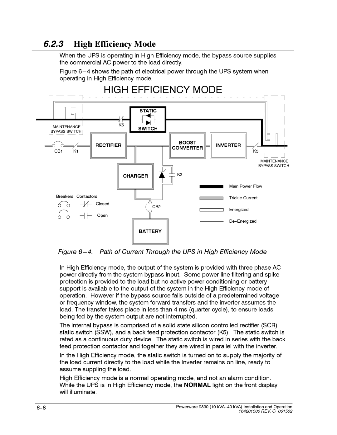
Figure 6---4 shows the path of electrical power through the UPS system when operating in High Efficiency mode.
HIGH EFFICIENCY MODE
|
| STATIC |
MAINTENANCE | K5 | SWITCH |
| ||
BYPASS SWITCH |
| |
|
|
RECTIFIER | BOOST | INVERTER | |
CONVERTER | |||
CB1 K1 | K3 | ||
|
MAINTENANCE
BYPASS SWITCH
CHARGER | K2 |
Main Power Flow
Breakers Contactors |
|
Closed | CB2 |
| |
Open |
|
BATTERY
Trickle Current
Energized
Figure 6 ---4. Path of Current Through the UPS in High Efficiency Mode
In High Efficiency mode, the output of the system is provided with three phase AC power directly from the system bypass input. Some power line filtering and spike protection is provided to the load but no active power conditioning or battery support is available to the output of the system in the High Efficiency mode of operation. However if the bypass source falls outside of a predetermined voltage or frequency window, the system forward transfers and the inverter assumes the load. The transfer takes place in less than 4 ms (quarter cycle), to ensure loads being fed by the system output are not interrupted.
The internal bypass is comprised of a solid state silicon controlled rectifier (SCR) static switch (SSW), and a back feed protection contactor (K5). The static switch is rated as a continuous duty device. The static switch is wired in series with the back feed protection contactor and together they are wired in parallel with the inverter.
In the High Efficiency mode, the static switch is turned on to supply the majority of the load current directly to the load while the Inverter remains on line, ready to assume suppling the load.
High Efficiency mode is a normal operating mode, and not an alarm condition. While the UPS is in High Efficiency mode, the NORMAL light on the front display will illuminate.
Powerware 9330 (10 | |
| 164201300 REV. G 061502 |