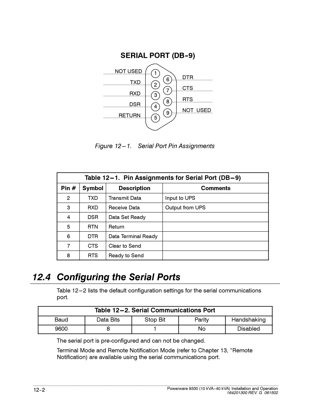
SERIAL PORT (DB-9)
NOT USED | 1 |
| DTR |
|
| ||
TXD |
| 6 | |
2 |
| ||
| CTS | ||
| 7 | ||
RXD |
| ||
3 |
| ||
| RTS | ||
|
| ||
DSR |
| 8 | |
4 |
| ||
| NOT USED | ||
|
| ||
RETURN |
| 9 | |
5 |
| ||
|
| ||
|
|
|
Figure 12 ---1. Serial Port Pin Assignments
| |||
|
|
|
|
Pin # | Symbol | Description | Comments |
|
|
|
|
2 | TXD | Transmit Data | Input to UPS |
|
|
|
|
3 | RXD | Receive Data | Output from UPS |
|
|
|
|
4 | DSR | Data Set Ready |
|
|
|
|
|
5 | RTN | Return |
|
|
|
|
|
6 | DTR | Data Terminal Ready |
|
|
|
|
|
7 | CTS | Clear to Send |
|
|
|
|
|
8 | RTS | Ready to Send |
|
|
|
|
|
12.4 Configuring the Serial Ports
Table
Table 12---2. Serial Communications Port
Baud 9600
Data Bits
8
Stop Bit
1
Parity
No
Handshaking
Disabled
The serial port is
Terminal Mode and Remote Notification Mode (refer to Chapter 13, “Remote Notification) are available using the serial communications port.
Powerware 9330 (10 | |
| 164201300 REV. G 061502 |
