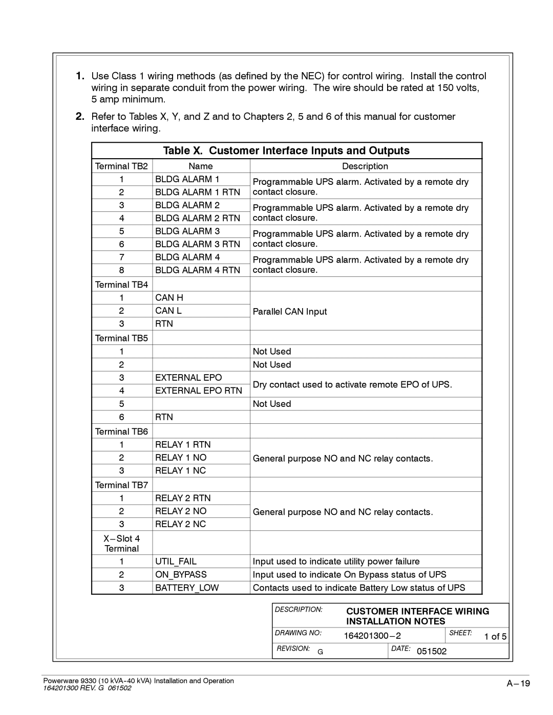
1.Use Class 1 wiring methods (as defined by the NEC) for control wiring. Install the control wiring in separate conduit from the power wiring. The wire should be rated at 150 volts, 5 amp minimum.
2.Refer to Tables X, Y, and Z and to Chapters 2, 5 and 6 of this manual for customer interface wiring.
|
| Table X. Customer Interface Inputs and Outputs |
|
|
| ||||
|
|
|
|
|
|
|
|
| |
| Terminal TB2 | Name |
|
| Description |
|
|
| |
|
|
|
|
| |||||
| 1 | BLDG ALARM 1 | Programmable UPS alarm. Activated by a remote dry |
| |||||
| 2 | BLDG ALARM 1 RTN | contact closure. |
|
|
|
|
| |
| 3 | BLDG ALARM 2 | Programmable UPS alarm. Activated by a remote dry |
| |||||
| 4 | BLDG ALARM 2 RTN | contact closure. |
|
|
|
|
| |
| 5 | BLDG ALARM 3 | Programmable UPS alarm. Activated by a remote dry |
| |||||
| 6 | BLDG ALARM 3 RTN | contact closure. |
|
|
|
|
| |
| 7 | BLDG ALARM 4 | Programmable UPS alarm. Activated by a remote dry |
| |||||
| 8 | BLDG ALARM 4 RTN | contact closure. |
|
|
|
|
| |
| Terminal TB4 |
|
|
|
|
|
|
|
|
|
|
|
|
|
|
|
|
|
|
| 1 | CAN H |
|
|
|
|
|
|
|
|
|
|
|
|
|
|
|
| |
| 2 | CAN L | Parallel CAN Input |
|
|
|
|
| |
| 3 | RTN |
|
|
|
|
|
|
|
|
|
|
|
|
|
|
|
|
|
| Terminal TB5 |
|
|
|
|
|
|
|
|
|
|
|
|
|
|
|
|
| |
| 1 |
| Not Used |
|
|
|
|
| |
| 2 |
| Not Used |
|
|
|
|
| |
|
|
|
|
|
|
|
|
|
|
| 3 | EXTERNAL EPO | Dry contact used to activate remote EPO of UPS. |
| |||||
| 4 | EXTERNAL EPO RTN |
| ||||||
|
|
|
|
|
|
|
| ||
| 5 |
| Not Used |
|
|
|
|
| |
|
|
|
|
|
|
|
|
|
|
| 6 | RTN |
|
|
|
|
|
|
|
| Terminal TB6 |
|
|
|
|
|
|
|
|
|
|
|
|
|
|
|
|
|
|
| 1 | RELAY 1 RTN |
|
|
|
|
|
|
|
|
|
|
|
| |||||
| 2 | RELAY 1 NO | General purpose NO and NC relay contacts. |
| |||||
| 3 | RELAY 1 NC |
|
|
|
|
|
|
|
| Terminal TB7 |
|
|
|
|
|
|
|
|
|
|
|
|
|
|
|
|
|
|
| 1 | RELAY 2 RTN |
|
|
|
|
|
|
|
|
|
|
|
| |||||
| 2 | RELAY 2 NO | General purpose NO and NC relay contacts. |
| |||||
| 3 | RELAY 2 NC |
|
|
|
|
|
|
|
|
|
|
|
|
|
|
|
|
|
|
|
|
|
|
|
|
|
| |
| Terminal |
|
|
|
|
|
|
|
|
| 1 | UTIL_FAIL | Input used to indicate utility power failure |
| |||||
|
|
|
|
| |||||
| 2 | ON_BYPASS | Input used to indicate On Bypass status of UPS |
| |||||
|
|
|
|
| |||||
| 3 | BATTERY_LOW | Contacts used to indicate Battery Low status of UPS |
| |||||
|
|
|
|
|
|
|
|
|
|
|
|
|
| DESCRIPTION: | CUSTOMER INTERFACE WIRING | ||||
|
|
|
|
| INSTALLATION NOTES |
| |||
|
|
|
| DRAWING NO: |
| SHEET: | 1 of 5 | ||
|
|
|
|
|
|
| |||
|
|
|
|
|
|
|
|
|
|
|
|
|
| REVISION: G |
| DATE: | 051502 |
| |
Powerware 9330 (10 | |
164201300 REV. G 061502 |
|
