6.2.1Normal Mode
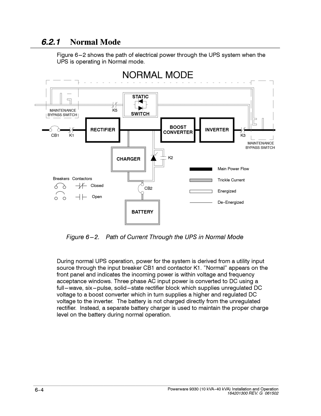
Figure 6---2 shows the path of electrical power through the UPS system when the UPS is operating in Normal mode.
NORMAL MODE
|
| STATIC |
MAINTENANCE | K5 | SWITCH |
BYPASS SWITCH |
|
RECTIFIER | BOOST | INVERTER | |
CONVERTER | |||
CB1 K1 | K3 | ||
| |||
|
| MAINTENANCE | |
|
| BYPASS SWITCH | |
CHARGER | K2 |
| |
|
| Main Power Flow |
Breakers Contactors |
|
Closed | CB2 |
| |
Open |
|
BATTERY
Trickle Current
Energized
Figure 6 ---2. Path of Current Through the UPS in Normal Mode
During normal UPS operation, power for the system is derived from a utility input source through the input breaker CB1 and contactor K1. ”Normal” appears on the front panel and indicates the incoming power is within voltage and frequency acceptance windows. Three phase AC input power is converted to DC using a
Powerware 9330 (10 | |
| 164201300 REV. G 061502 |