1 SYSTEM CONFIGURATION
System Configuration
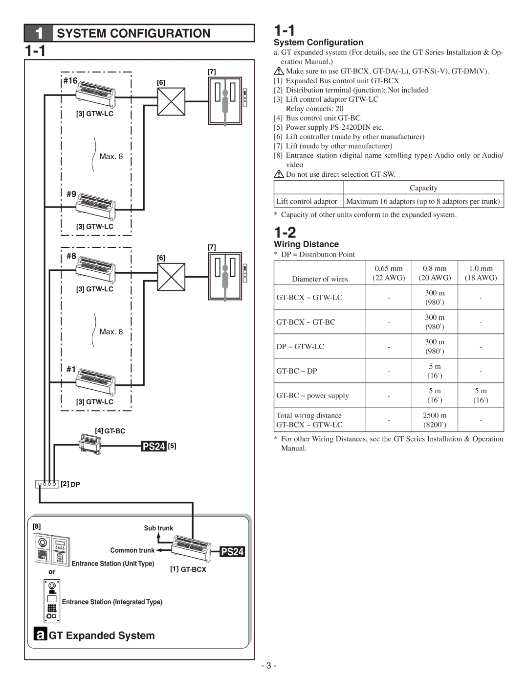
a. GT expanded system (For details, see the GT Series Installation & Op- eration Manual.)
#16 |
[3] |
Max. 8 |
#9 |
[3] |
#8 |
[3]
Max. 8
#1
[3]
[4]
[7]
[6]
[7]
[6]
![]() Make sure to use
Make sure to use
[1]Expanded Bus control unit
[2]Distribution terminal (junction): Not included
[3]Lift control adaptor
[4]Bus control unit
[5]Power supply
[6]Lift controller (made by other manufacturer)
[7]Lift (made by other manufacturer)
[8]Entrance station (digital name scrolling type): Audio only or Audio/ video
Do not use direct selection
Capacity
Lift control adaptor Maximum 16 adaptors (up to 8 adaptors per trunk)
* Capacity of other units conform to the expanded system.
Wiring Distance
* DP = Distribution Point
| 0.65 mm | 0.8 mm | 1.0 mm | |
Diameter of wires | (22 AWG) | (20 AWG) | (18 AWG) | |
|
|
|
| |
- | 300 m | - | ||
(980’) | ||||
|
|
| ||
|
|
|
| |
- | 300 m | - | ||
(980’) | ||||
|
|
| ||
|
|
|
| |
DP ~ | - | 300 m | - | |
(980’) | ||||
|
|
| ||
|
|
|
| |
- | 5 m | - | ||
(16’) | ||||
|
|
| ||
|
|
|
| |
- | 5 m | 5 m | ||
(16’) | (16’) | |||
|
| |||
|
|
|
| |
Total wiring distance | - | 2500 m | - | |
(8200’) | ||||
|
| |||
|
|
|
|
PS24 [5]
![]()
![]()
![]()
![]()
![]()
![]() [2] DP
[2] DP
[8]Sub trunk
4 | 5 | 6 | Common trunk | PS24 |
1 | 2 | 3 |
| |
7 | 8 | 9 | Entrance Station (Unit Type) |
|
| 0 |
|
| |
or |
|
|
| [1] |
Entrance Station (Integrated Type)
a GT Expanded System
*For other Wiring Distances, see the GT Series Installation & Operation Manual.
- 3 -
