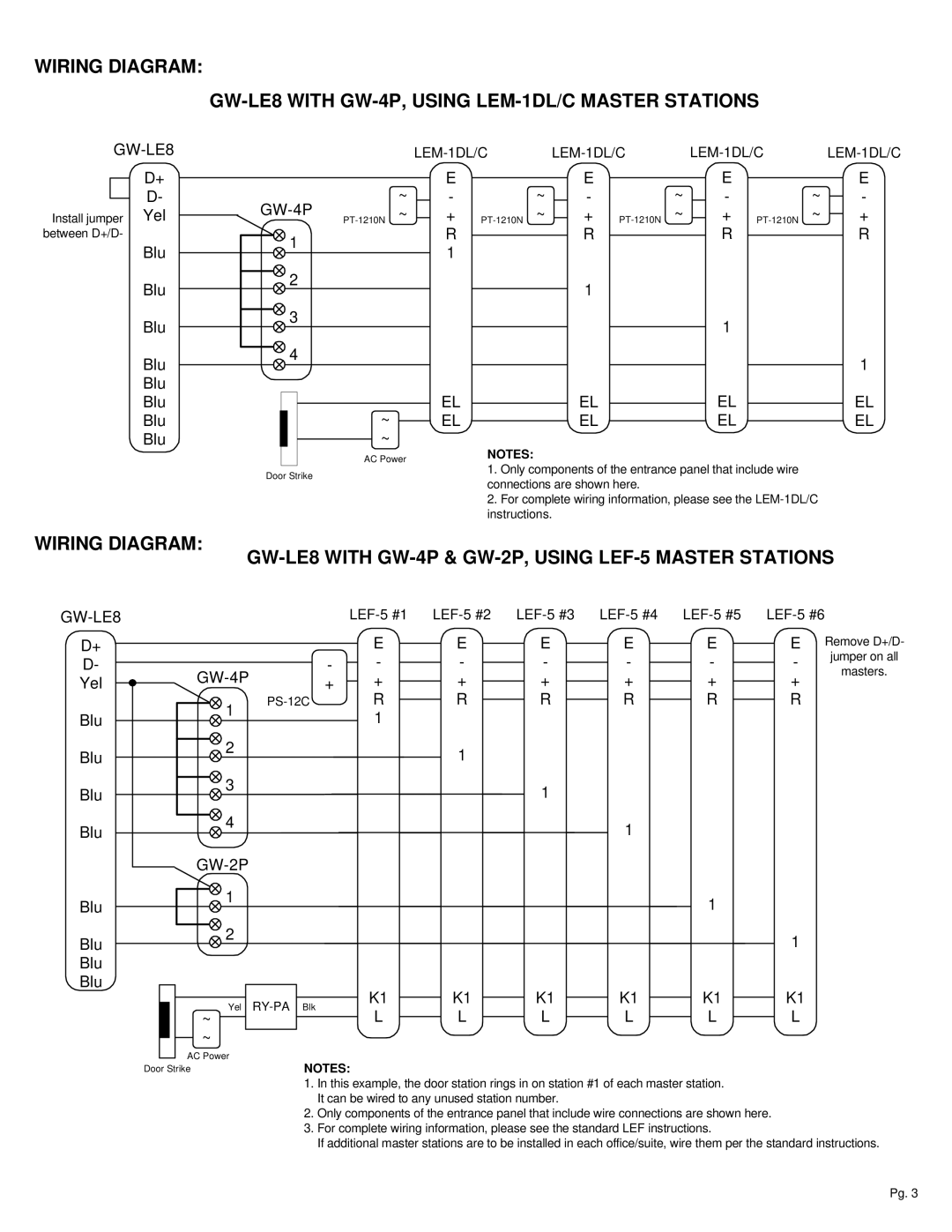
WIRING DIAGRAM:
D+
D-
Install jumper Yel between D+/D-
Blu
Blu
Blu
Blu
Blu
Blu
Blu
Blu
LEM-1DL/C LEM-1DL/C LEM-1DL/C LEM-1DL/C
~ | E | ~ | E | ~ | E | ~ | E |
- | - | - | - | ||||
+ | + | + | + | ||||
1 | R |
| R |
| R |
| R |
1 |
|
|
|
|
|
| |
|
|
|
|
|
|
| |
2 |
|
| 1 |
|
|
|
|
|
|
|
|
|
|
| |
3 |
|
|
|
| 1 |
|
|
|
|
|
|
|
|
| |
4 |
|
|
|
|
|
| 1 |
|
|
|
|
|
|
| |
~ | EL |
| EL |
| EL |
| EL |
EL |
| EL |
| EL |
| EL | |
~ |
| NOTES: |
|
|
|
|
|
AC Power |
|
|
|
|
|
| |
|
|
|
|
|
|
|
Door Strike
1. Only components of the entrance panel that include wire connections are shown here.
2.For complete wiring information, please see the
WIRING DIAGRAM:
D+
D-
Yel
Blu
Blu
Blu
Blu
Blu
|
|
| |||||||
|
| E | E | E | E | E | E Remove D+/D- | ||
| - | - | - | - | - | - | - | jumper on all | |
masters. | |||||||||
+ | + | + | + | + | + | + | |||
| |||||||||
1 | R | R | R | R | R | R |
| ||
| 1 |
|
|
|
|
|
| ||
|
|
|
|
|
|
|
| ||
2 |
|
| 1 |
|
|
|
|
| |
|
|
|
|
|
|
|
| ||
3 |
|
|
| 1 |
|
|
|
| |
|
|
|
|
|
|
|
| ||
4 |
|
|
|
| 1 |
|
|
| |
|
|
|
|
|
|
|
| ||
|
|
|
|
|
|
|
| ||
1 |
|
|
|
|
| 1 |
|
| |
|
|
|
|
|
|
|
| ||
Blu
Blu
Blu
2 | 1 |
|
Yel | K1 | K1 | K1 | K1 | K1 | K1 | |
Blk | L | L | L | L | L | ||
~ |
| L | |||||
~ |
|
|
|
|
|
|
|
AC Power |
|
|
|
|
|
|
|
Door Strike | NOTES: | |
| 1. | In this example, the door station rings in on station #1 of each master station. |
|
| It can be wired to any unused station number. |
| 2. | Only components of the entrance panel that include wire connections are shown here. |
| 3. | For complete wiring information, please see the standard LEF instructions. |
|
| If additional master stations are to be installed in each office/suite, wire them per the standard instructions. |
Pg. 3