WIRING
Forced Entry | (See Note 4) | ||
Sensor Input |
| ||
(See Note 2) | |||
(Egress) Input |
| ||
Forced Entry | (See Note 4) | ||
Trigger Out |
| ||
Night Lock | (See Note 3) | ||
Trigger Out |
| ||
|
|
| (See Note 1) |
|
|
| |
|
|
| DC Power | |
Strike | ||||
| ||||
Grey |
|
|
|
Green |
|
|
|
Grey / Pink |
|
|
|
Red / Blue |
|
|
|
Violet (Lock) |
|
|
|
Brown (Ground) |
| White: | Not Used |
| Red | Yellow: | Not Used |
+ | Pink: | Not Used | |
Black | Blue: | Not Used | |
- |
|
| |
12V DC |
|
| |
Power Supply |
|
| |
NOTES:
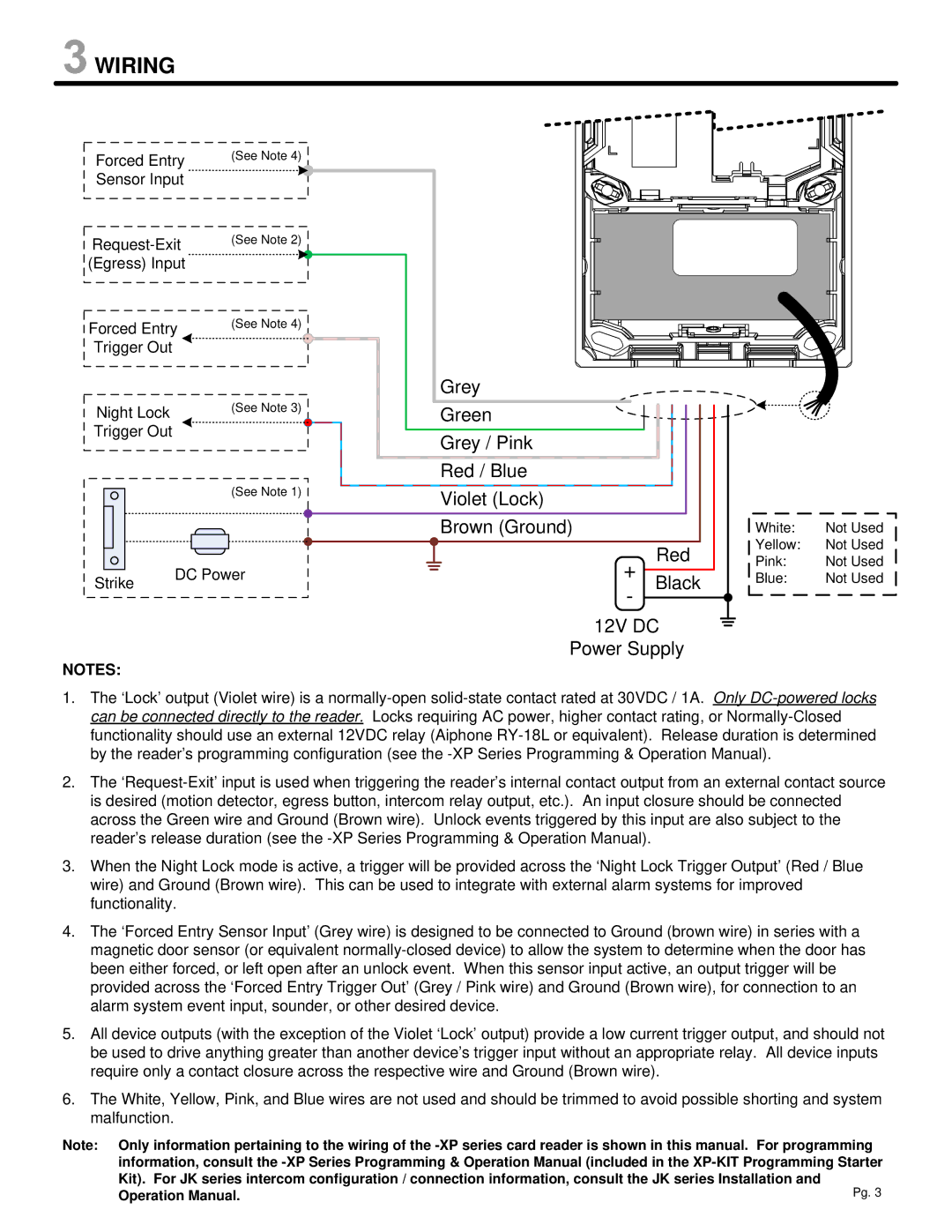
1.The ‘Lock’ output (Violet wire) is a
2.The
3.When the Night Lock mode is active, a trigger will be provided across the ‘Night Lock Trigger Output’ (Red / Blue wire) and Ground (Brown wire). This can be used to integrate with external alarm systems for improved functionality.
4.The ‘Forced Entry Sensor Input’ (Grey wire) is designed to be connected to Ground (brown wire) in series with a magnetic door sensor (or equivalent
5.All device outputs (with the exception of the Violet ‘Lock’ output) provide a low current trigger output, and should not be used to drive anything greater than another device’s trigger input without an appropriate relay. All device inputs require only a contact closure across the respective wire and Ground (Brown wire).
6.The White, Yellow, Pink, and Blue wires are not used and should be trimmed to avoid possible shorting and system malfunction.
Note: Only information pertaining to the wiring of the