LEM-1DL specifications
The Aiphone LEM-1DL is a versatile intercom system designed for residential and light commercial applications. Renowned for its reliability and user-friendly features, this unit provides an efficient communication solution, making it a popular choice among both homeowners and businesses.At its core, the LEM-1DL integrates advanced audio technology that ensures clear communication between users. The high-quality speaker and microphone deliver crisp sound, reducing the likelihood of miscommunication. Users appreciate the adjustable volume control, which allows for personalized audio levels depending on the environment or individual preference.
One of the standout features of the Aiphone LEM-1DL is its simple, sleek design that blends seamlessly into any setting. The unit is mounted on a wall, providing easy access without taking up valuable space. The illuminated doorbell button is an added convenience, allowing guests to alert occupants with ease, even in low-light conditions.
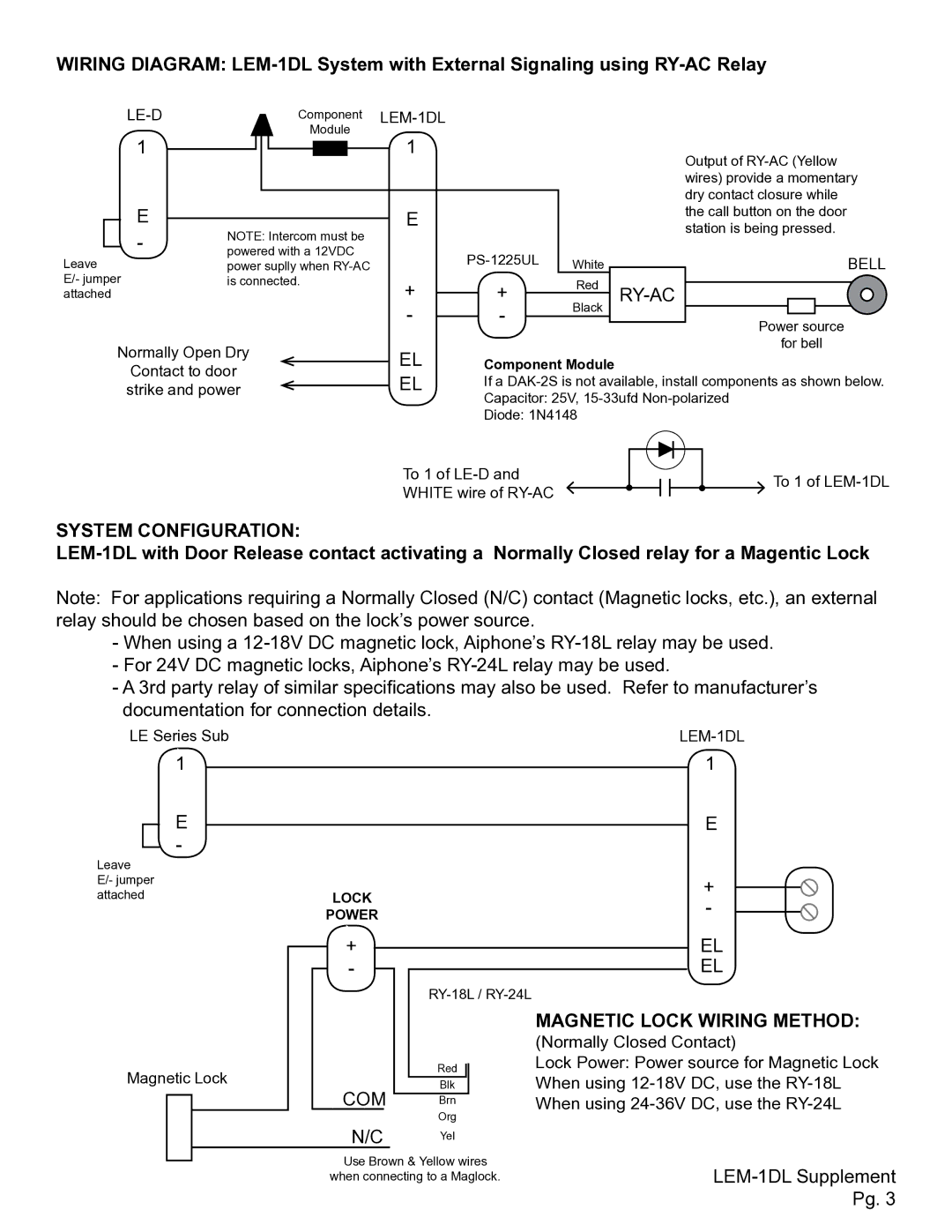
The LEM-1DL operates on a 2-wire system, which simplifies installation and reduces overall costs. The simplified wiring process ensures that even those with limited technical know-how can set up the system. Additionally, the use of a common 16V AC power supply further enhances the installation efficiency, making it a practical addition for a variety of settings.
In terms of functionality, the LEM-1DL supports up to two entrance panels and can interconnect with up to four additional LEM-1DL stations, allowing for comprehensive communication throughout a building. This scalability makes it ideal for larger homes or small businesses, where multiple points of communication are essential.
Furthermore, the system includes a push-to-talk feature, which makes conversations straightforward and practical. Users simply press the talk button to communicate, ensuring a smooth and effective dialogue. The unit also includes a visual indicator for when the system is active, a useful feature for managing communication effectively.
In summary, the Aiphone LEM-1DL is a robust intercom system that prioritizes clarity, ease of installation, and user-friendliness. Its modern design, coupled with advanced features and functionalities, makes it an excellent choice for anyone looking to enhance communication in their home or business environment. The combination of high-quality audio, convenience, and scalability ensures that the LEM-1DL is a reliable solution, catering to various communication needs.

