1205
10 Camera Adaptor for LEF/LDF System
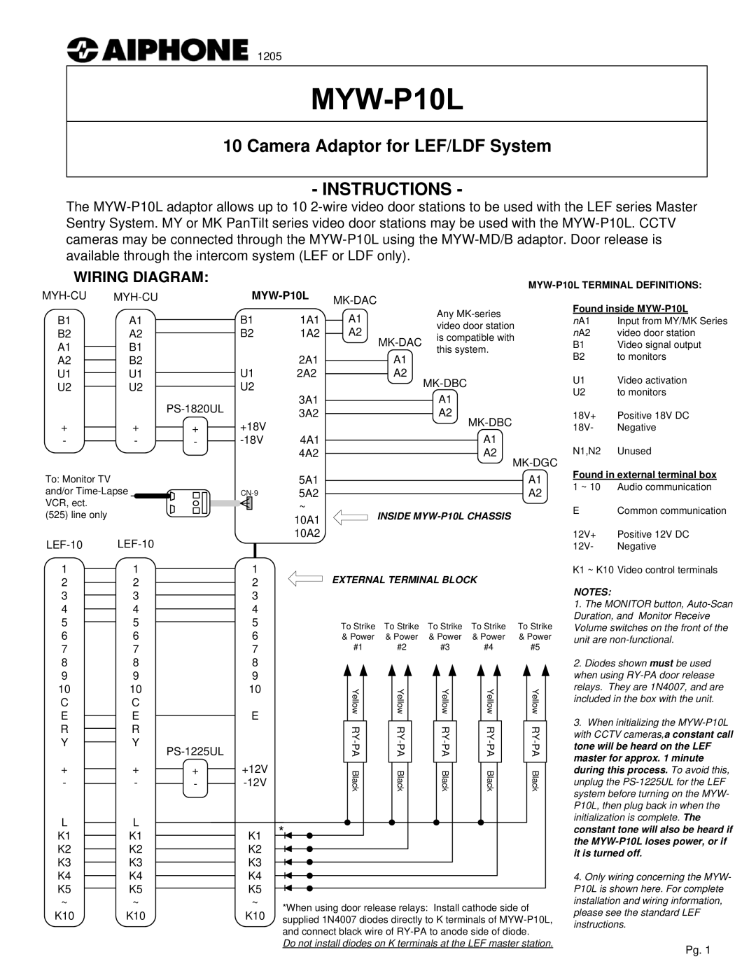
- INSTRUCTIONS -
The
WIRING DIAGRAM:
| |
B1 | A1 |
B2 | A2 |
A1 | B1 |
A2 | B2 |
U1 | U1 |
U2 | U2 |
|
| |
+ | + | + |
- | - | - |
|
|
|
|
| Found inside | ||||
|
|
|
|
| Any | ||||
B1 |
| 1A1 |
| A1 |
|
| |||
|
|
|
| nA1 | Input from MY/MK Series | ||||
|
|
|
| video door station | |||||
B2 |
| 1A2 | A2 |
|
| nA2 | video door station | ||
| is compatible with | ||||||||
|
|
|
|
| B1 | Video signal output | |||
|
|
|
|
| this system. | ||||
|
| 2A1 |
|
|
| A1 | B2 | to monitors | |
|
|
|
|
|
| ||||
U1 |
| 2A2 |
|
| A2 |
| U1 | Video activation | |
U2 |
|
|
|
|
|
| |||
|
|
|
|
|
| U2 | to monitors | ||
|
| 3A1 |
|
|
|
| A1 | ||
|
|
|
|
|
|
|
| ||
|
| 3A2 |
|
|
|
| A2 | 18V+ | Positive 18V DC |
+18V |
|
|
|
|
|
| 18V- | Negative | |
| 4A1 |
|
|
|
| A1 | N1,N2 | Unused | |
|
| 4A2 |
|
|
|
| A2 | ||
|
|
|
|
|
|
|
|
|
|
To: Monitor TV and/or
(525) line only
11
22
33
44
55
66
77
88
99
10 | 10 |
|
C | C |
|
E | E |
|
R | R |
|
Y | Y | |
|
| |
+ | + | + |
- | - | - |
L | L |
|
K1 | K1 |
|
K2 | K2 |
|
K3 | K3 |
|
K4 | K4 |
|
K5 | K5 |
|
~ | ~ |
|
K10 | K10 |
|
1
2
3
4
5
6
7
8
9
10
E
+12V
K1
K2
K3
K4
K5
~
K10
5A1 | A1 |
5A2 | A2 |
~ | INSIDE |
10A1 | |
10A2 |
|
EXTERNAL TERMINAL BLOCK
To Strike | To Strike | To Strike | To Strike | To Strike | ||||||||||||||||||
& Power | & Power | & Power | & Power | & Power | ||||||||||||||||||
#1 |
|
| #2 |
|
| #3 |
|
| #4 |
|
| #5 |
| |||||||||
|
| Yellow |
|
|
|
| Yellow |
|
|
|
| Yellow |
|
|
| Yellow |
|
|
|
| Yellow |
|
|
|
|
|
|
|
|
|
|
|
|
|
|
|
|
|
|
| |||||
|
|
|
|
|
|
|
|
|
|
|
|
|
|
|
|
|
|
|
|
|
|
|
|
|
|
|
|
|
|
|
|
|
|
|
|
| |||||||||
|
|
|
|
|
|
|
|
|
|
|
|
|
|
|
|
|
|
|
|
|
|
|
|
| Black |
|
| Black |
|
| Black |
| Black |
|
| Black | |||||||||
|
|
|
|
|
|
|
|
|
|
|
|
|
|
|
|
|
|
|
|
|
|
|
*![]()
*When using door release relays: Install cathode side of supplied 1N4007 diodes directly to K terminals of
Do not install diodes on K terminals at the LEF master station.
Found in external terminal box 1 ~ 10 Audio communication
E Common communication
12V+ Positive 12V DC
12V- Negative
K1 ~ K10 Video control terminals
NOTES:
1.The MONITOR button,
2.Diodes shown must be used when using
3.When initializing the
4.Only wiring concerning the MYW- P10L is shown here. For complete installation and wiring information, please see the standard LEF instructions.
Pg. 1