3 INSTALLATION
1.Mount the amplifier on a wall or base plate capable of supporting its weight securely. Be sure no heat producing elements are nearby. Also be sure that the area behind the amplifier allows a clear path of air to flow and that the air slots at the top and bottom are not obstructed.
IMPORTANT: To comply with NRTL/C safety regulations, a minimum clearance of 6 inches must be maintained above the unit. (See picture at right.)
2.Loosen, but do not remove the screw at the bottom of the unit to gain access to the terminals and switches under the lower cover.
3.Lift the cover all the way up. In the fully open position you can conveniently refer to the labelling which indicates the terminal connections and dip switch settings.
6"
(Airflow)
4.Make all the proper connections, determined by which system is being used in conjunction with the amplifier. (As you make your connections, the small "plate" rises from the bottom of the terminal to secure the wire.)
5.Connect the speaker line to the terminals labelled OUTPUT.
6.Set all appropriate switches and volume levels. (Refer to Names and Functions section.)
4 WIRING DIAGRAMS
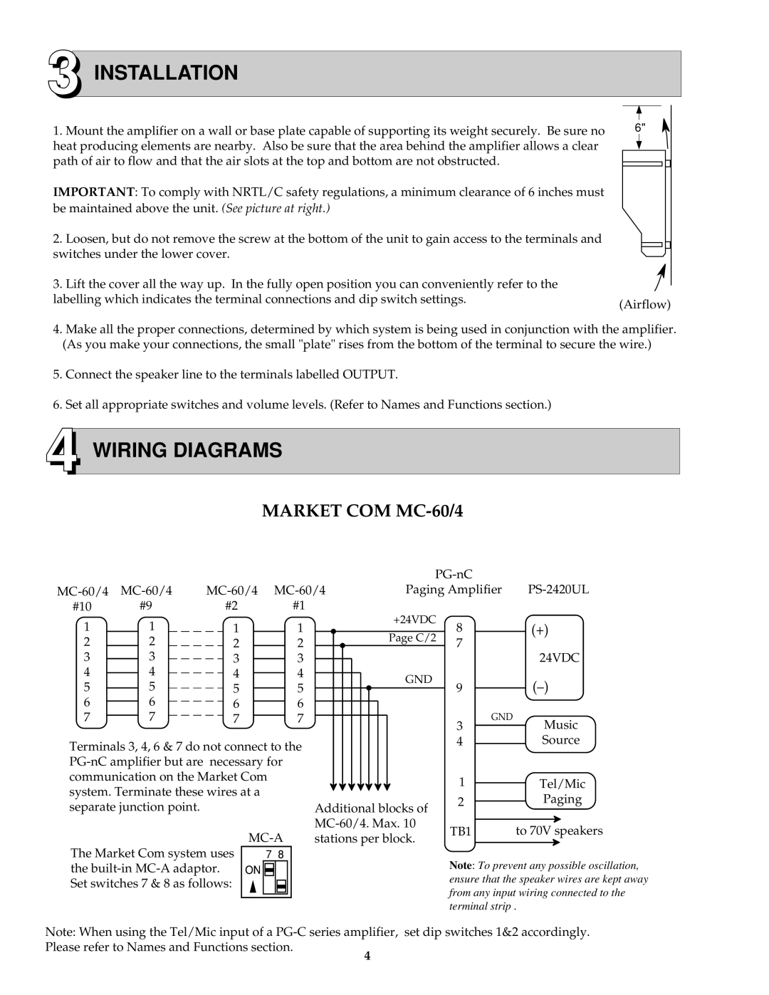
MARKET COM MC-60/4
|
|
|
|
|
|
|
|
|
|
|
|
|
|
|
|
|
|
|
|
|
|
|
|
|
|
|
|
|
|
|
| |||
|
|
|
|
|
|
| Paging Amplifier | |||||||||||||||||||||||||||
#10 |
|
|
| #9 |
|
| #2 |
|
| #1 |
|
|
|
|
|
|
| +24VDC |
|
|
|
| ||||||||||||
1 |
|
|
|
| 1 |
|
|
|
|
|
|
|
|
|
|
|
|
|
|
|
|
|
|
|
|
|
| |||||||
|
|
|
|
|
| 1 |
|
| 1 |
|
|
|
|
|
|
|
| 8 | (+) |
|
| |||||||||||||
| 2 |
|
|
|
| 2 |
|
| 2 |
|
| 2 |
|
|
|
|
|
|
| Page C/2 | 7 |
|
|
|
| |||||||||
3 |
|
|
|
| 3 |
|
|
|
|
|
| 24VDC | ||||||||||||||||||||||
|
|
|
|
|
|
| 3 |
|
| 3 |
|
|
|
|
|
|
|
|
|
|
|
| ||||||||||||
|
|
|
|
|
|
|
|
|
|
|
|
|
|
|
|
| ||||||||||||||||||
4 |
|
|
|
| 4 |
|
| 4 |
|
| 4 |
|
|
|
|
|
|
| GND |
|
|
| ||||||||||||
|
|
|
|
|
|
|
|
|
|
|
|
|
|
|
| |||||||||||||||||||
5 |
|
|
|
|
|
| 5 |
|
| 5 |
|
| 5 |
|
|
|
|
|
|
| 9 | |||||||||||||
|
|
|
|
|
|
|
|
|
|
|
|
|
|
|
|
| ||||||||||||||||||
|
|
|
|
|
|
|
|
|
|
|
|
|
|
|
|
|
| |||||||||||||||||
6 |
|
|
|
|
| 6 |
|
| 6 |
|
| 6 |
|
|
|
|
|
|
|
|
|
|
|
|
|
|
| |||||||
|
|
|
|
|
|
|
|
|
|
|
|
|
|
|
|
|
|
| ||||||||||||||||
7 |
|
|
|
|
| 7 |
|
| 7 |
|
| 7 |
|
|
|
|
|
|
|
|
|
| GND |
|
| Music | ||||||||
|
|
|
|
|
|
|
|
|
|
|
|
|
| |||||||||||||||||||||
|
|
|
|
|
|
|
|
|
|
|
|
|
|
|
|
|
|
|
|
|
|
|
|
|
|
|
|
| 3 |
|
| |||
Terminals 3, 4, 6 & 7 do not connect to the |
|
|
|
|
|
|
|
|
| 4 |
|
| Source | |||||||||||||||||||||
|
|
|
|
|
|
|
|
|
|
|
|
|
|
| ||||||||||||||||||||
|
|
|
|
|
|
|
|
|
|
|
|
|
|
| ||||||||||||||||||||
communication on the Market Com |
|
|
|
|
|
|
|
|
| 1 |
|
| Tel/Mic | |||||||||||||||||||||
system. Terminate these wires at a |
|
|
|
|
|
|
|
|
|
|
|
|
|
|
|
|
| |||||||||||||||||
|
|
|
|
|
|
|
|
|
|
|
|
|
|
| 2 |
|
| Paging | ||||||||||||||||
separate junction point. |
|
|
|
|
|
|
|
|
| Additional blocks of |
|
|
| |||||||||||||||||||||
|
|
|
|
|
|
|
|
|
|
|
|
|
|
|
| |||||||||||||||||||
|
|
|
|
|
|
|
|
|
|
|
|
|
|
|
|
|
|
|
|
|
|
|
|
|
|
| ||||||||
|
|
|
|
|
|
|
|
|
|
|
|
|
|
| TB1 | to 70V speakers | ||||||||||||||||||
|
|
|
|
|
|
|
|
|
|
|
|
| stations per block. |
| ||||||||||||||||||||
The Market Com system uses |
|
|
|
|
|
|
|
| ||||||||||||||||||||||||||
|
|
|
|
|
|
|
|
|
|
|
|
|
|
|
|
|
|
|
|
|
|
| ||||||||||||
|
| 7 8 |
|
|
|
|
|
|
|
|
|
|
| Note: To prevent any possible oscillation, | ||||||||||||||||||||
the |
| ON |
|
|
|
|
|
|
|
|
|
|
|
|
|
| ||||||||||||||||||
Set switches 7 & 8 as follows: |
|
|
|
|
|
|
|
|
|
|
|
|
|
|
|
| ensure that the speaker wires are kept away | |||||||||||||||||
|
|
|
|
|
|
|
|
|
|
|
|
|
|
|
| |||||||||||||||||||
|
|
|
|
|
|
|
|
|
|
|
|
|
|
|
| |||||||||||||||||||
|
|
|
|
|
|
|
|
|
|
|
|
|
|
|
| from any input wiring connected to the | ||||||||||||||||||
|
|
|
|
|
|
|
|
|
|
|
|
|
|
|
|
|
|
|
|
|
|
|
|
|
|
|
| |||||||
|
|
|
|
|
|
|
|
|
|
|
|
|
|
|
|
|
|
|
|
|
|
|
|
|
|
|
| |||||||
|
|
|
|
|
|
|
|
|
|
|
|
|
|
|
|
|
|
|
|
|
|
|
|
|
|
|
| |||||||
|
|
|
|
|
|
|
|
|
|
|
|
|
|
|
|
|
|
|
|
|
|
|
|
|
|
|
| terminal strip . | ||||||
Note: When using the Tel/Mic input of a
Please refer to Names and Functions section.
4