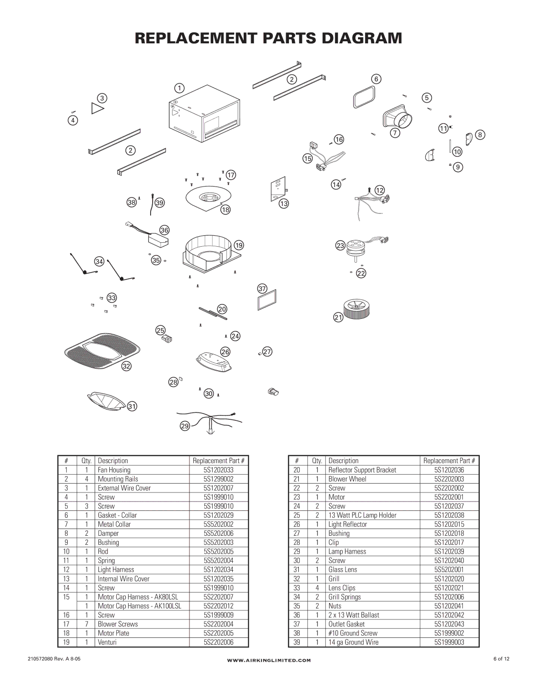
REPLACEMENT PARTS DIAGRAM
|
| 2 | 6 |
|
| 1 |
|
3 |
|
| 5 |
4 |
|
|
|
|
|
| 7 |
|
|
| 16 |
2 |
|
|
|
|
|
| 15 |
|
| 17 |
|
|
|
| 14 |
|
|
| 12 |
38 | 39 | 13 |
|
|
| 18 |
|
| 36 |
|
|
|
| 19 | 23 |
34 | 35 |
|
|
|
|
| 22 |
37
33
20
21 ![]()
25
24
26 | 27 |
32
28
30
31
29
11
10
9
8
# | Qty. | Description | Replacement Part # |
1 | 1 | Fan Housing | 5S1202033 |
2 | 4 | Mounting Rails | 5S1299002 |
3 | 1 | External Wire Cover | 5S1202007 |
4 | 1 | Screw | 5S1999010 |
5 | 3 | Screw | 5S1999010 |
6 | 1 | Gasket - Collar | 5S1202029 |
7 | 1 | Metal Collar | 5S5202002 |
8 | 2 | Damper | 5S5202006 |
9 | 2 | Bushing | 5S5202003 |
10 | 1 | Rod | 5S5202005 |
11 | 1 | Spring | 5S5202004 |
12 | 1 | Light Harness | 5S1202034 |
13 | 1 | Internal Wire Cover | 5S1202035 |
14 | 1 | Screw | 5S1999010 |
15 | 1 | Motor Cap Harness - AK80LSL | 5S2202007 |
| 1 | Motor Cap Harness - AK100LSL | 5S2202012 |
16 | 1 | Screw | 5S1999009 |
17 | 7 | Blower Screws | 5S2202004 |
18 | 1 | Motor Plate | 5S2202005 |
19 | 1 | Venturi | 5S2202006 |
# | Qty. | Description | Replacement Part # |
20 | 1 | Reflector Support Bracket | 5S1202036 |
21 | 1 | Blower Wheel | 5S2202003 |
22 | 2 | Screw | 5S2202002 |
23 | 1 | Motor | 5S2202001 |
24 | 2 | Screw | 5S1202037 |
25 | 2 | 13 Watt PLC Lamp Holder | 5S1202038 |
26 | 1 | Light Reflector | 5S1202015 |
27 | 1 | Bushing | 5S1202018 |
28 | 1 | Clip | 5S1202017 |
29 | 1 | Lamp Harness | 5S1202039 |
30 | 2 | Screw | 5S1202040 |
31 | 1 | Glass Lens | 5S5202001 |
32 | 1 | Grill | 5S1202020 |
33 | 4 | Lens Clips | 5S1202021 |
34 | 2 | Grill Springs | 5S1202006 |
35 | 2 | Nuts | 5S1202041 |
36 | 1 | 2 x 13 Watt Ballast | 5S1202042 |
37 | 1 | Outlet Gasket | 5S1202043 |
38 | 1 | #10 Ground Screw | 5S1999002 |
39 | 1 | 14 ga Ground Wire | 5S1999003 |
210572080 Rev. A | www.airkinglimited.com | 6 of 12 |
