SECTION 4
Ducting
CAUTION: ALL DUCTING MUST COMPLY WITH LOCAL AND NATIONAL BUILDING CODES.
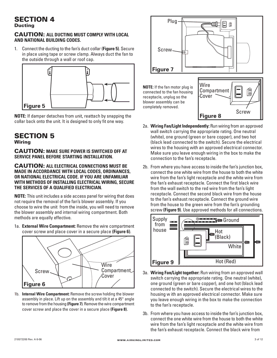
1.Connect the ducting to the fan’s duct collar (Figure 5). Secure in place using tape or screw clamp. Always duct the fan to the outside through a wall or roof cap.
Figure 5
NOTE: If damper detaches from unit, reattach by snapping the collar back onto the unit. It is designed to only fit one way.
SECTION 5
Wiring
CAUTION: MAKE SURE POWER IS SWITCHED OFF AT SERVICE PANEL BEFORE STARTING INSTALLATION.
CAUTION: ALL ELECTRICAL CONNECTIONS MUST BE MADE IN ACCORDANCE WITH LOCAL CODES, ORDINANCES, OR NATIONAL ELECTRICAL CODE. IF YOU ARE UNFAMILIAR WITH METHODS OF INSTALLING ELECTRICAL WIRING, SECURE THE SERVICES OF A QUALIFIED ELECTRICIAN.
NOTE: This unit includes a side access panel for wiring that does not require the removal of the fan’s blower assembly. If you choose to wire the unit from the inside, you will need to remove the blower assembly and internal wiring compartment. Both methods are equally effective.
1a. External Wire Compartment: Remove the wire compartment cover screw and place cover in a secure place (Figure 6).
Wire
ScrewCompartment
Cover
Figure 6
1b. Internal Wire Compartment: Remove the screw holding the blower assembly in place. Lift up on the assembly and tilt it at a 45° angle to remove from the housing (Figure 7). Remove the wire compartment cover screw and place the cover in a secure place (Figure 8).
Plug 
Screw
Figure 7
NOTE: If the fan motor plug is |
| Wire |
connected to the fan housing |
| Compartment |
receptacle, unplug so the |
| Cover |
| ||
blower assembly can be |
|
|
completely removed. |
|
|
Screw
Figure 8
2a. Wiring Fan/Light Independently: Run wiring from an approved wall switch carrying the appropriate rating. One neutral (white), one ground (green or bare copper), and two hot (black lead connected to the switch). Secure the electrical wires to the housing with an approved electrical connector. Make sure you leave enough wiring in the box to make the connection to the fan’s receptacle.
2b. From where you have access to inside the fan’s junction box, connect the one white wire from the house to both the white wire from the fan’s light receptacle and the white wire from the fan’s exhaust receptacle. Connect the first black wire from the wall switch to the red wire from the fan’s light receptacle. Connect the second black wire from the house to the fan’s exhaust receptacle. Connect the ground wire from the house to the green wire from the fan’s grounding screw (Figure 9). Use approved methods for all connections.
Supply | Ground |
from |
|
house | Hot |
| (Black) |
| White |
Figure 9 | Hot (Red) |
3a. Wiring Fan/Light together: Run wiring from an approved wall switch carrying the appropriate rating. One neutral (white), one ground (green or bare copper), and one hot (black lead connected to the switch). Secure the electrical wires to the housing w ith an approved electrical connector. Make sure you leave enough wiring in the box to make the connection to the fan’s receptacle.
3b. From where you have access to inside the fan’s junction box, connect the one white wire from the house to both the white wire from the fan’s light receptacle and the white wire from the fan’s exhaust receptacle. Connect the black wire from
210572200 Rev. A | www.airkinglimited.com | 3 of 12 |