REPLACEMENT PARTS DIAGRAM
4 7 8
3
2
1
5
6
17
15
9 | 18 |
1410
19
16
13
11 | 20 |
12 | 21 |
22
24
23
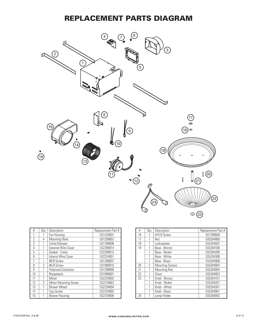
# | Qty. | Description | Replacement Part # |
1 | 1 | Fan Housing | 5S1234001 |
2 | 4 | Mounting Rails | 5S1299002 |
3 | 1 | Collar/Damper | 5S1299006 |
4 | 1 | External Wire Cover | 5S2299014 |
5 | 1 | Gasket - Collar | 5S2299015 |
6 | 1 | Interior Wire Cover | 5S2234001 |
7 | 1 | #8 B Screw | 5S1299007 |
8 | 2 | #6 B Screw | 5S1999010 |
9 | 1 | Polarized Connector | 5S1299008 |
10 | 1 | Receptacle | 5S1999001 |
11 | 1 | Motor | 5S2234002 |
12 | 3 | Motor Mounting Screw | 5S2234003 |
13 | 1 | Blower Wheel | 5S2234004 |
14 | 1 | Cap Screw | 5S2234005 |
15 | 1 | Blower Housing | 5S2234006 |
# | Qty. | Description | Replacement Part # |
16 | 1 | #10 B Screw | 5S1299009 |
17 | 1 | Nut | 5S5204008 |
18 | 1 | Lockwasher | 5S5204007 |
19 | 1 | Base - Bronze | 5S5204106 |
| 1 | Base - Nickel | 5S5204206 |
| 1 | Base - White | 5S5204306 |
| 1 | Base - Brass | 5S5204906 |
20 | 2 | Mounting Screws | 5S5204004 |
21 | 1 | Mounting Rod | 5S5204005 |
22 | 1 | Glass | 5S5204003 |
23 | 1 | Knob - Bronze | 5S5204101 |
| 1 | Knob - Nickel | 5S5204201 |
| 1 | Knob - White | 5S5204301 |
| 1 | Knob - Brass | 5S5204901 |
24 | 1 | Lamp Holder | 5S5204002 |
210572200 Rev. A | www.airkinglimited.com | 6 of 12 |