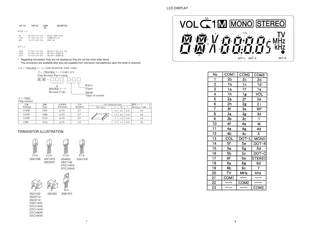
CSD-TD52, CSD-TD53, CSD-TD51 specifications
The Aiwa CSD-TD51, CSD-TD53, and CSD-TD52 are a triumvirate of compact stereo cassette players that evoke nostalgia while integrating modern technology for an enhanced audio experience. These models, crafted with precision by Aiwa, a brand renowned for its dedication to quality audio equipment, cater to both audiophiles and casual listeners alike.Starting with the CSD-TD51, this model is characterized by its dual cassette deck design, allowing users to play and record from one cassette to another effortlessly. It features high-speed dubbing, which significantly reduces the time taken to create duplicates of favorite tapes. The CSD-TD51 includes a built-in AM/FM tuner that offers a wide range of radio stations, providing access to various music genres and talk shows. Its robust speakers deliver rich sound quality, making it ideal for both intimate listening sessions and larger gatherings.
Moving on to the CSD-TD52, this model adds a modern twist with a sleek, compact design that fits beautifully into any room setting. The CSD-TD52 also supports both cassette playback and recording, ensuring that users can enjoy old favorite tapes or create mixes from their current collections. Notably, the incorporation of a digital clock and programmable memory adds convenience, allowing users to set times for playback and manage their listening experience more effectively. The sound quality remains a hallmark, with enhanced bass response, thanks to the innovative speaker system integrated within the unit.
Finally, the CSD-TD53 serves as the flagship of this trio, featuring advanced audio technologies such as Dolby Noise Reduction, which minimizes tape hiss for a cleaner sound. This model also includes additional features such as a CD player, expanding the listening options to include CDs and tapes alike. The CSD-TD53 supports various media formats, making it a versatile addition to any home or personal audio setup. With an elegant design and user-friendly interface, the CSD-TD53 is perfect for those who appreciate vintage tape technology while also wanting contemporary features.
Overall, the Aiwa CSD series is a testament to the brand's commitment to quality sound and design. These models not only revitalize the classic cassette experience but also incorporate features that cater to today's technology-driven music lovers, ensuring that timeless tunes are accessible in a modern format. Whether you are a nostalgic user or a new fan of cassette culture, these Aiwa models deliver a unique blend of past and present in one compact audio solution.

