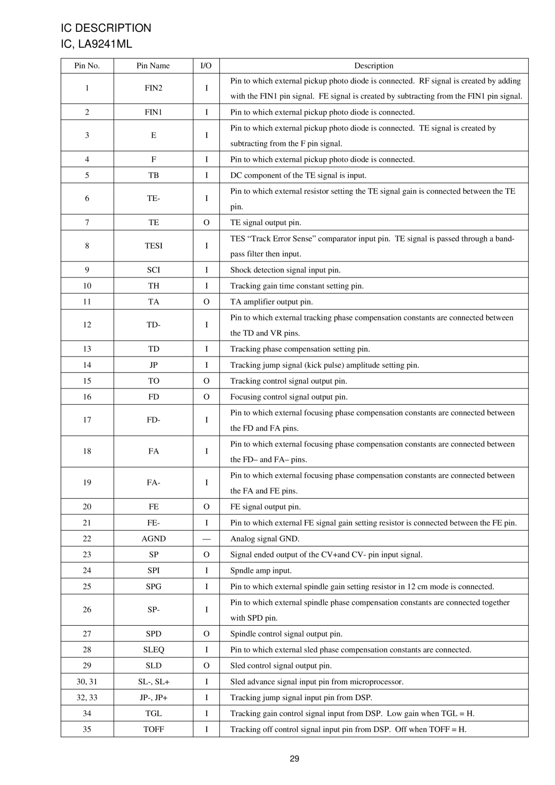
IC DESCRIPTION

IC, LA9241ML

Pin No.

Pin Name

I/O

Description


1

FIN2

I

Pin to which external pickup photo diode is connected. RF signal is created by adding

with the FIN1 pin signal. FE signal is created by subtracting from the FIN1 pin signal.


2

FIN1

I

Pin to which external pickup photo diode is connected.


3

E

I

Pin to which external pickup photo diode is connected. TE signal is created by

subtracting from the F pin signal.


4

F

I

Pin to which external pickup photo diode is connected.


5

TB

I

DC component of the TE signal is input.


6

TE-

I

Pin to which external resistor setting the TE signal gain is connected between the TE

pin.


7

TE

O

TE signal output pin.


8

TESI

I

TES “Track Error Sense” comparator input pin. TE signal is passed through a band-

pass filter then input.


9

SCI

I

Shock detection signal input pin.


10

TH

I

Tracking gain time constant setting pin.


11

TA

O

TA amplifier output pin.


12

TD-

I

Pin to which external tracking phase compensation constants are connected between

the TD and VR pins.


13

TD

I

Tracking phase compensation setting pin.


14

JP

I

Tracking jump signal (kick pulse) amplitude setting pin.


15

TO

O

Tracking control signal output pin.


16

FD

O

Focusing control signal output pin.


17

FD-

I

Pin to which external focusing phase compensation constants are connected between

the FD and FA pins.


18

FA

I

Pin to which external focusing phase compensation constants are connected between

the FD– and FA– pins.


19

FA-

I

Pin to which external focusing phase compensation constants are connected between

the FA and FE pins.


20

FE

O

FE signal output pin.


21

FE-

I

Pin to which external FE signal gain setting resistor is connected between the FE pin.


22

AGND

Analog signal GND.


23

SP

O

Signal ended output of the CV+and CV- pin input signal.


24

SPI

I

Spndle amp input.


25

SPG

I

Pin to which external spindle gain setting resistor in 12 cm mode is connected.


26

SP-

I

Pin to which external spindle phase compensation constants are connected together

with SPD pin.


27

SPD

O

Spindle control signal output pin.


28

SLEQ

I

Pin to which external sled phase compensation constants are connected.


29

SLD

O

Sled control signal output pin.


30, 31

SL-, SL+

I

Sled advance signal input pin from microprocessor.


32, 33

JP-, JP+

I

Tracking jump signal input pin from DSP.


34

TGL

I

Tracking gain control signal input from DSP. Low gain when TGL = H.


35

TOFF

I

Tracking off control signal input pin from DSP. Off when TOFF = H.


29

Page 19
Image 19
Aiwa CSD-TD53, CSD-TD51, CSD-TD52 service manual IC Description

CSD-TD52, CSD-TD53, CSD-TD51 specifications

The Aiwa CSD-TD51, CSD-TD53, and CSD-TD52 are a triumvirate of compact stereo cassette players that evoke nostalgia while integrating modern technology for an enhanced audio experience. These models, crafted with precision by Aiwa, a brand renowned for its dedication to quality audio equipment, cater to both audiophiles and casual listeners alike.

Starting with the CSD-TD51, this model is characterized by its dual cassette deck design, allowing users to play and record from one cassette to another effortlessly. It features high-speed dubbing, which significantly reduces the time taken to create duplicates of favorite tapes. The CSD-TD51 includes a built-in AM/FM tuner that offers a wide range of radio stations, providing access to various music genres and talk shows. Its robust speakers deliver rich sound quality, making it ideal for both intimate listening sessions and larger gatherings.

Moving on to the CSD-TD52, this model adds a modern twist with a sleek, compact design that fits beautifully into any room setting. The CSD-TD52 also supports both cassette playback and recording, ensuring that users can enjoy old favorite tapes or create mixes from their current collections. Notably, the incorporation of a digital clock and programmable memory adds convenience, allowing users to set times for playback and manage their listening experience more effectively. The sound quality remains a hallmark, with enhanced bass response, thanks to the innovative speaker system integrated within the unit.

Finally, the CSD-TD53 serves as the flagship of this trio, featuring advanced audio technologies such as Dolby Noise Reduction, which minimizes tape hiss for a cleaner sound. This model also includes additional features such as a CD player, expanding the listening options to include CDs and tapes alike. The CSD-TD53 supports various media formats, making it a versatile addition to any home or personal audio setup. With an elegant design and user-friendly interface, the CSD-TD53 is perfect for those who appreciate vintage tape technology while also wanting contemporary features.

Overall, the Aiwa CSD series is a testament to the brand's commitment to quality sound and design. These models not only revitalize the classic cassette experience but also incorporate features that cater to today's technology-driven music lovers, ensuring that timeless tunes are accessible in a modern format. Whether you are a nostalgic user or a new fan of cassette culture, these Aiwa models deliver a unique blend of past and present in one compact audio solution.