!Installation – MPC4000
1.Remove the fixing screws of the MPC4000 Side Pan- els (4pcs. on each side) and remove Side Panels. Next, remove the screws (5pcs. on each side) hidden by the Side Panels and then remove the center screws (2pcs.) located underneath the Armrest and the topmost of Rear Panel. The Top Panel Block can be
2.Remove the fixing screws (4pcs.) for the Mask Plate (upper slot) on the Rear Panel and remove the Mask Plate. Save the screws for later use. The Mask Plate is not used.
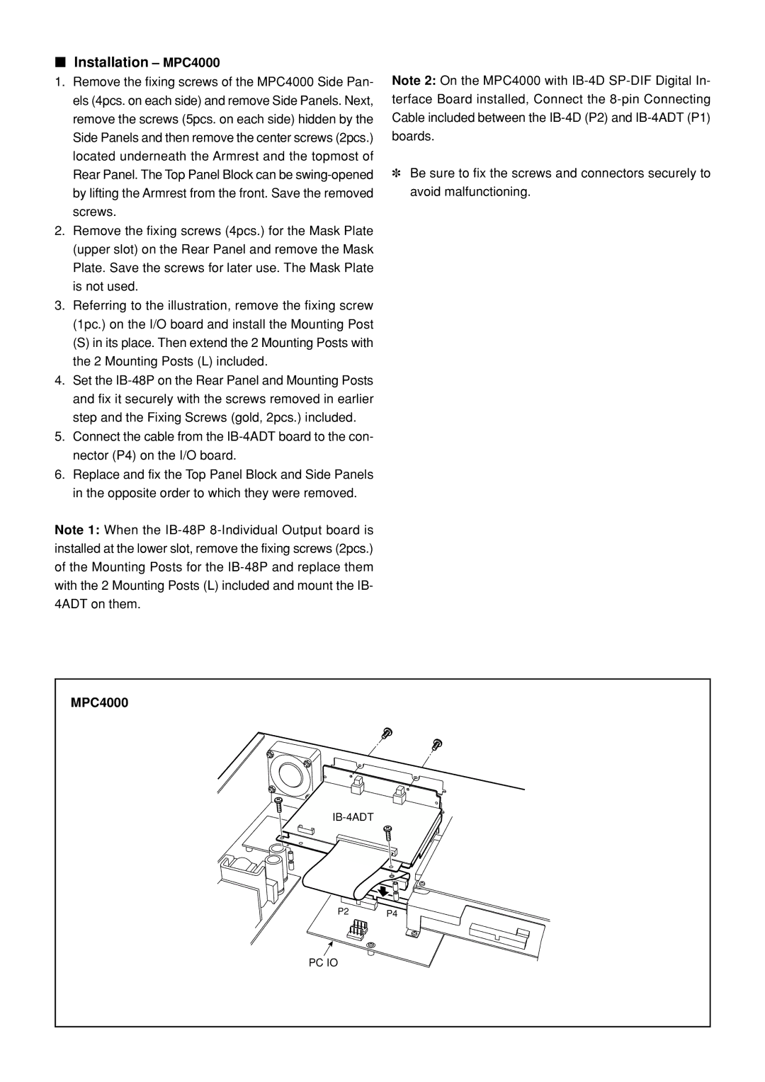
3.Referring to the illustration, remove the fixing screw (1pc.) on the I/O board and install the Mounting Post
(S) in its place. Then extend the 2 Mounting Posts with the 2 Mounting Posts (L) included.
4.Set the
5.Connect the cable from the
6.Replace and fix the Top Panel Block and Side Panels in the opposite order to which they were removed.
Note 1: When the
Note 2: On the MPC4000 with
✽Be sure to fix the screws and connectors securely to avoid malfunctioning.
MPC4000
P2 P4
PC IO