6000 OAW-LC-2G24F specifications
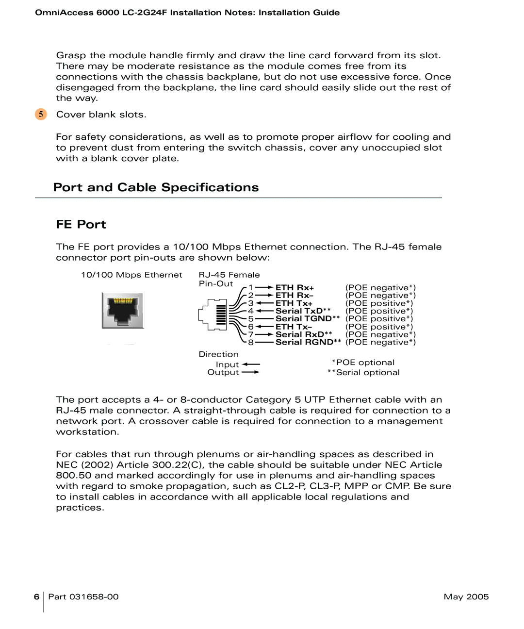
The Alcatel Carrier Internetworking Solutions 6000 OAW-LC-2G24F is a robust networking solution designed to facilitate efficient and reliable communication in various environments. This solution is particularly well-suited for carriers, large enterprises, and service providers looking to optimize their network connectivity and performance.One of the main features of the OAW-LC-2G24F is its high port density. With 24 Gigabit Ethernet (GE) ports, this device offers substantial connectivity options, allowing organizations to connect numerous devices without the need for additional switches. The architecture of the OAW-LC-2G24F is designed to support both Layer 2 and Layer 3 functionalities, providing flexibility in network design and implementation.
Additionally, this networking solution integrates advanced Quality of Service (QoS) capabilities, ensuring data packets are prioritized effectively. This is particularly crucial for service providers that manage voice, video, and data traffic simultaneously. The device is equipped with features that support traffic shaping, allowing it to manage bandwidth allocation dynamically based on current network demands.
The OAW-LC-2G24F utilizes various technologies such as Virtual LAN (VLAN), Spanning Tree Protocol (STP), and Link Aggregation Control Protocol (LACP). VLAN support allows for segmentation of network traffic, improving security and performance by isolating different groups of users or applications. STP and LACP contribute to network resilience and efficiency by preventing loops and ensuring optimal utilization of bandwidth.
In terms of scalability, the Alcatel OAW-LC-2G24F can easily adapt to growing network requirements. Its modular design allows for future upgrades and additional functionalities without necessitating a complete hardware replacement. This characteristic is vital for organizations that anticipate increasing demands over time.
Furthermore, the OAW-LC-2G24F comes equipped with comprehensive management tools that facilitate the monitoring and configuration of the network. These tools enable network administrators to respond swiftly to potential issues, optimize performance, and maintain the overall health of the network.
In conclusion, the Alcatel Carrier Internetworking Solutions 6000 OAW-LC-2G24F stands out for its high port density, advanced QoS capabilities, and robust management features. Designed for scalability and flexibility, it is an ideal choice for organizations aiming to enhance their networking infrastructure and ensure smooth, efficient, and reliable communications.

