AVR
Safety Information
Outdoor Antenna Grounding. If an outside antenna
Important Safety Information
Staple Invoice Here
Table of Contents
Introduction
Thank you for choosing Harman Kardon
Audio Section
Surround Modes
Supplied Accessories
Audio Inputs
Audio/Video Inputs With S-Video
Digital Audio Inputs
FRONT-PANEL Controls
Navigation Adjust Input Indicators
Main Power
Coaxial Video Switch Select
Audio Inputs
REAR-PANEL Connections
Video 1, Video 2, Video 3 and DVD Audio/Video Inputs
REAR-PANEL Connections
DVD A/V
Bridge/DMP Controls an iPod docked in The Bridge
Remote Control Functions
Channel Input Selector Press this button to select
DSP Surround On-Screen Display
Track Skip Transport Controls
Remote Control Functions
Introduction to Home Theater
Surround Modes
Typical Home Theater System
Multichannel Audio
Connecting Source Devices to the AVR
Connections
Types of Connections
Speaker Connections
Audio Connections
Digital Audio
Analog Video
Video Connections
Digital Video
RS-232 Serial Port
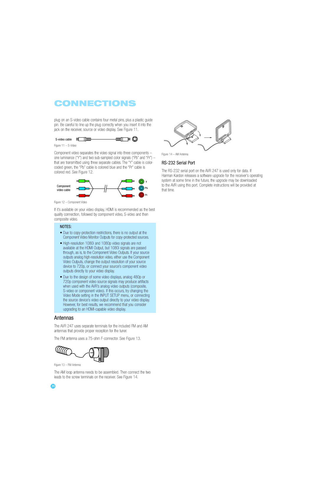
FM antenna uses a 75-ohm F-connector. See Figure
Antennas
Speaker Placement
Placement of Surround Speakers in a 5.1-Channel System
Front Speaker Placement
Placement of Surround Speakers in a 7.1-Channel System
Subwoofer Placement
Installation
Step One Connect the Speakers
Step Two Connect the Subwoofer
Step Three Connect the Antennas
Recommended Source Component Connections
Audio Connections Video Connections
TiVo or other Or Video 1 Composite Video Input
Video Video 2 Analog Inputs
Video 1 Source
Video 3 Source
Video 2 Source
Video 4 Source
No video connections are needed
Hdmi 1
Tape
Step Six Plug in AC Power
Step Five Connect the Video Display
Step Seven Insert Batteries in Remote
Turn on your source device
Video Cable, Satellite
Step Ten Install a Multiroom System Optional
Enter a code from , above
Two steps are required the first time you turn on the AVR
Press the Standby/On Switch on the front panel. See Figure
Step Eleven Turn On the AVR
Initial Setup
Using the On-Screen Menu System
Configure the AVR 247 Using EzSet/EQ
EzSet/EQ Screen
What EzSet/EQ Does
Terminals
Configure Sources
EzSet/EQ Equalization
Source Input Default Video Input
Only upper case letters are available for titles
Source Input
Coax
You are now ready to begin enjoying your new receiver
Sleep Timer
Volume Control
Operation
Turning On the AVR
Source Selection
Headphones
Tone Controls
Channel Direct Inputs
Audio Input Selection
Video Input Selection
Using the Tuner
We recommend that you connect this player as follows
XM Radio Operation
To store a station in one of the 30 presets see Figure
Use the Numeric Keys to enter the desired preset number
Recording
Using TheBridgeTM
To store a channel in one of the 40 preset locations
IPod Function
Selecting a Surround Mode
Analog Audio Signals
Digital Audio Signals
Advanced Functions
Audio Processing and Surround Sound
Repeated Surround Setup Menu Screen
Night Mode
Default Modes
Dolby Surround Settings
Mode Group
Panorama adjusts wraparound surround effect Dolby Pro Logic
0 or
Dolby Digital EX played as
Surround Mode Description Incoming Bitstream or Signal
Mode Group Enveloping sound field is desired
Dolby Digital 2/0/.0 or
Reference
Mode Group
Appropriate when a subwoofer is used
DTS Neo6
DTS 2/2/.0 or .1, 3/2/.0 or
Manual Setup
Step Three Manual Setup Menu
Step One Determine Speaker Size
Step Two Measure Speaker Distances
Large setting
Speaker Size Menu
Move the cursor to the left to select the next submenu
Delay Adjust Menu
Speaker Crossover Menu
Step Four Setting Channel Output Levels Manually
Using the Remote Control With the Test Tone
However, if you prefer to make these adjustments manually,
Make sure all speakers have been connected correctly
Using the Full-OSD Menu
Video Adjustments
Using the Front-Panel or Remote-Control Channel Command
Installing a Multiroom System
Multiroom Operation
System Settings
Operating the Multiroom System
Advanced Remote Control Functions
Dim Function
Punch-Through Programming
To dim the display
Resetting the Remote
Processor Reset
Macros
Memory
Troubleshooting Guide
AVR 247 Technical Specifications
DTS
Appendix Default settings, worksheets, remote product codes
Table A1 Source Input Setting Defaults
Table A2 Speaker/Channel Setting Defaults
Table A3 Delay Setting Defaults
Table A4 Source Input Settings
Table A5 Speaker/Channel Settings
Auto Poll Surround Mode Tone Mode Bass Treble Video Mode
Title Video Input Audio Input
Table A6 Remote Control Codes
Table A7 System Settings
Tape Cassette
VCR, PVR, DVD, Cable, Satellite
Remote Control Function List Reference
Remote Control Function List
Table A8
Table A8
FAV
Aiwa
Table A9
Table A10 Remote Control Product Codes VCR
Table A11 Remote Control Product Codes CD
Table A13 Remote Control Product Codes SAT
Table A12 Remote Control Product Codes DVD
Table A16 Remote Control Product Codes
Table A15 Remote Control Product Codes CBL
Page