EC-2 96kHz A/D/D/A upgrade • appendix A
Prepare to install:
1 . Disconnect the HD24’s AC power cable, and make sure you are working on a clean, flat, hard surface. Ground yourself by touching a grounded metal object. An
Hazardous voltages are present within the chassis. Do not remove the top panel without first unplugging the unit from AC power!
2.Remove the cover from the HD24: The cover is held to the body with 5 Philips head screws on the rear, 2 on each side, and one on the top. Slide the cover directly towards the rear; don’t lift it
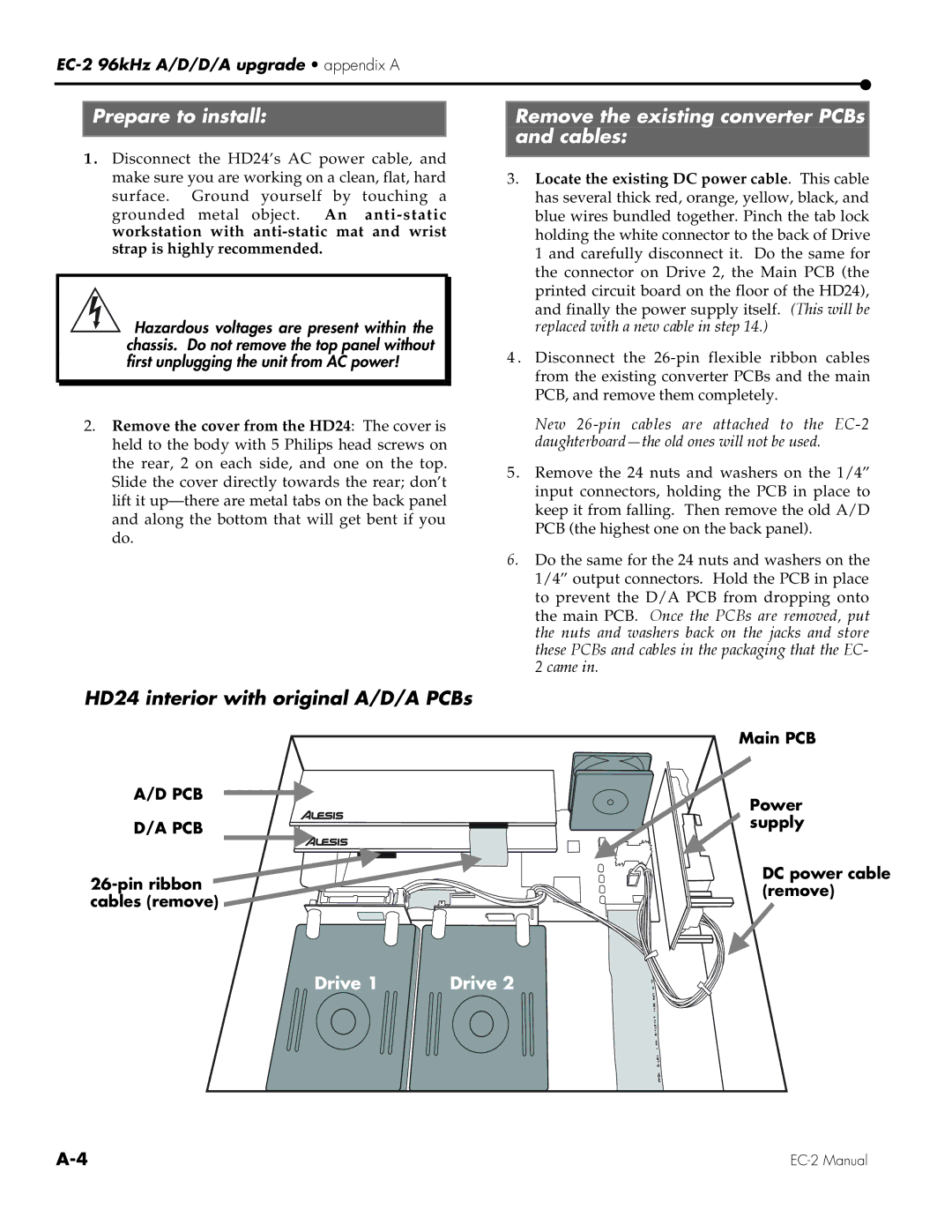
HD24 interior with original A/D/A PCBs
A/D PCB
D/A PCB
![]() cables (remove)
cables (remove) ![]()
![]()
Remove the existing converter PCBs and cables:
3.Locate the existing DC power cable. This cable has several thick red, orange, yellow, black, and blue wires bundled together. Pinch the tab lock holding the white connector to the back of Drive 1 and carefully disconnect it. Do the same for the connector on Drive 2, the Main PCB (the printed circuit board on the floor of the HD24), and finally the power supply itself. (This will be replaced with a new cable in step 14.)
4 . Disconnect the
New
5.Remove the 24 nuts and washers on the 1/4” input connectors, holding the PCB in place to keep it from falling. Then remove the old A/D PCB (the highest one on the back panel).
6.Do the same for the 24 nuts and washers on the 1/4” output connectors. Hold the PCB in place to prevent the D/A PCB from dropping onto the main PCB. Once the PCBs are removed, put the nuts and washers back on the jacks and store these PCBs and cables in the packaging that the EC- 2 came in.
Main PCB
Power ![]() supply
supply
DC power cable (remove)
Drive 1 | Drive 2 |
