appendix A •
Install the new EC-2 PCBs
7.Find the daughterboard in the
8 . Insert the ribbon connector labeled “J3 TO MAIN PCB” on the daughterboard into the 26- pin header labeled on the main PCB as “J14 TO D/A PCB”.
The headers on the main PCB sit near the back center, where the old input/output PCBs used to plug in. The red side of each cable should face the right of the HD24 (closest to the fan). Verify that the cables don’t have any twists in them and that there are no unconnected or exposed pins on the headers.
9. Lay the daughterboard gently on the PCBs at the rear of the hard drive cages until the Analog Input and Analog Output PCBs are installed.
10.Get the new Analog Output (D/A) PCB from its packaging. Remove the nuts and washers from the 1/4” connectors on the new Analog Output (D/A) PCB.
NOTE: The Analog Input and Analog Output PCBs look very similar. Verify that you have the correct PCB by looking for the part number and part name in the text in the corner of the PCB.
11.Place the Analog Output PCB in the bottom set of rear panel holes (labeled OUTPUT on the rear panel) with the components facing down (so that you can read the white text on the PCB, which says “D/A PCB” and “Analog Output”). Put a few of the washers and nuts on the 1/4” jacks to hold the PCB in place. Screw them down all the way, but do not tighten
12.Place the Analog Input PCB in the top set of rear panel holes (labeled INPUT on the rear panel) with the components facing down and put a few of the washers and nuts on the 1/4” jacks to hold the PCB in place. Screw them down all the way, but do not tighten.
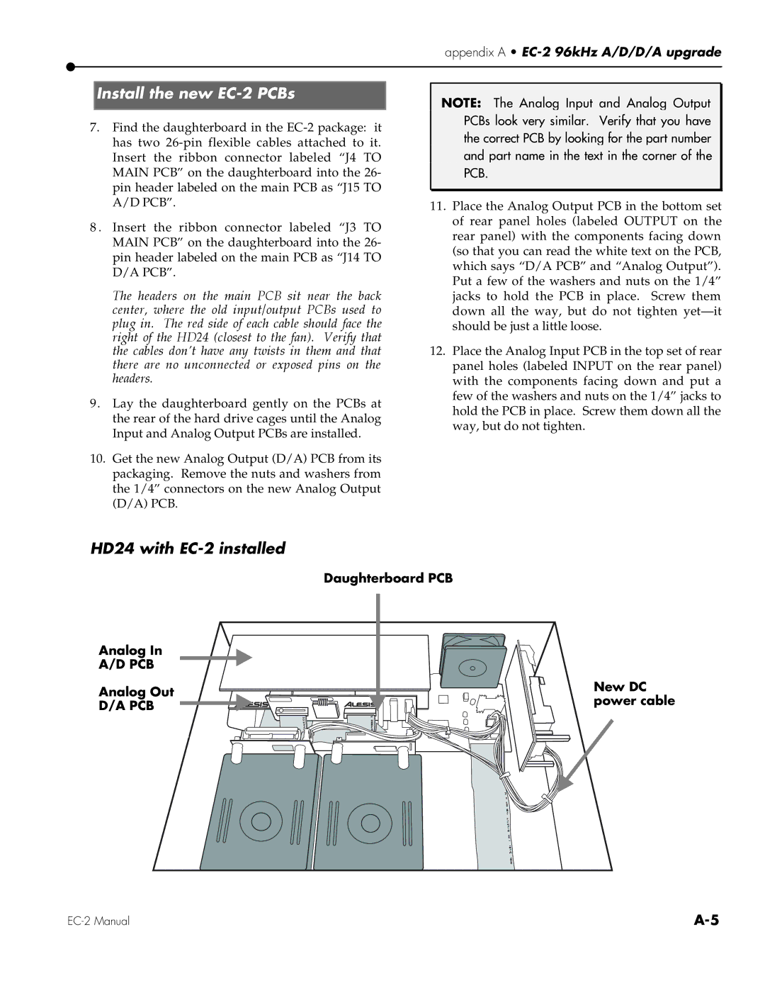
HD24 with EC-2 installed
Daughterboard PCB
Analog In
A/D PCB
Analog Out
D/A PCB
New DC power cable